Rod Pump System Design
Description
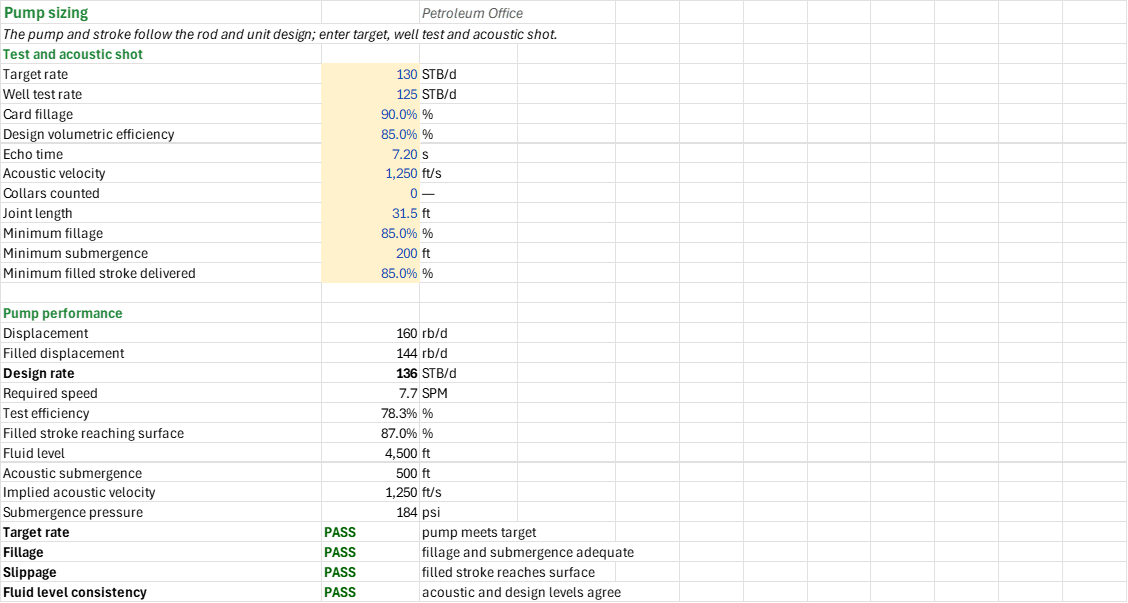
Will this rod string, pump and pumping unit lift the well's target rate without overloading the rods, the structure or the gearbox? You enter the plunger, the tapers, the fluid, the tubing-head pressure, the stroke and speed, the unit ratings, a well test and an acoustic shot. You read off the polished-rod loads and Goodman loading per taper, the effective stroke and pump rate, the fluid level, and the gearbox torque at the actual counterbalance. It is a screening calculation, not an equipment specification.
How to use it: On the Rods sheet, take the taper lengths and diameters from the rod tally, the grade and service factor from the installation and the fluid, and the pressure from the tubing-head gauge. On the System sheet, enter the unit's ratings and geometry from its nameplate. On the Pump sheet, enter a stabilised test rate, the card fillage and the echo time from an acoustic survey. On the Torque sheet, enter the actual counterbalance and compare the calculated torque with the manufacturer's torque factors and a measured dynamometer card. The Summary collects the design headlines and every check; a failing check overrides warnings.
Method: The rod string uses the Mills factors for peak and minimum polished-rod load and a modified Goodman stress check per taper. The fluid load acts on the plunger area over the net lift, which includes the tubing-head pressure. The effective plunger stroke is the surface stroke less rod and tubing stretch plus overtravel. The pump displacement and the unit torque follow from the linked design; the acoustic level is checked against the design submergence entered independently. The torque around the crank uses a sinusoidal torque factor and a rectangular card envelope, at the actual and at the ideal counterbalance.
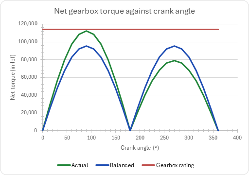
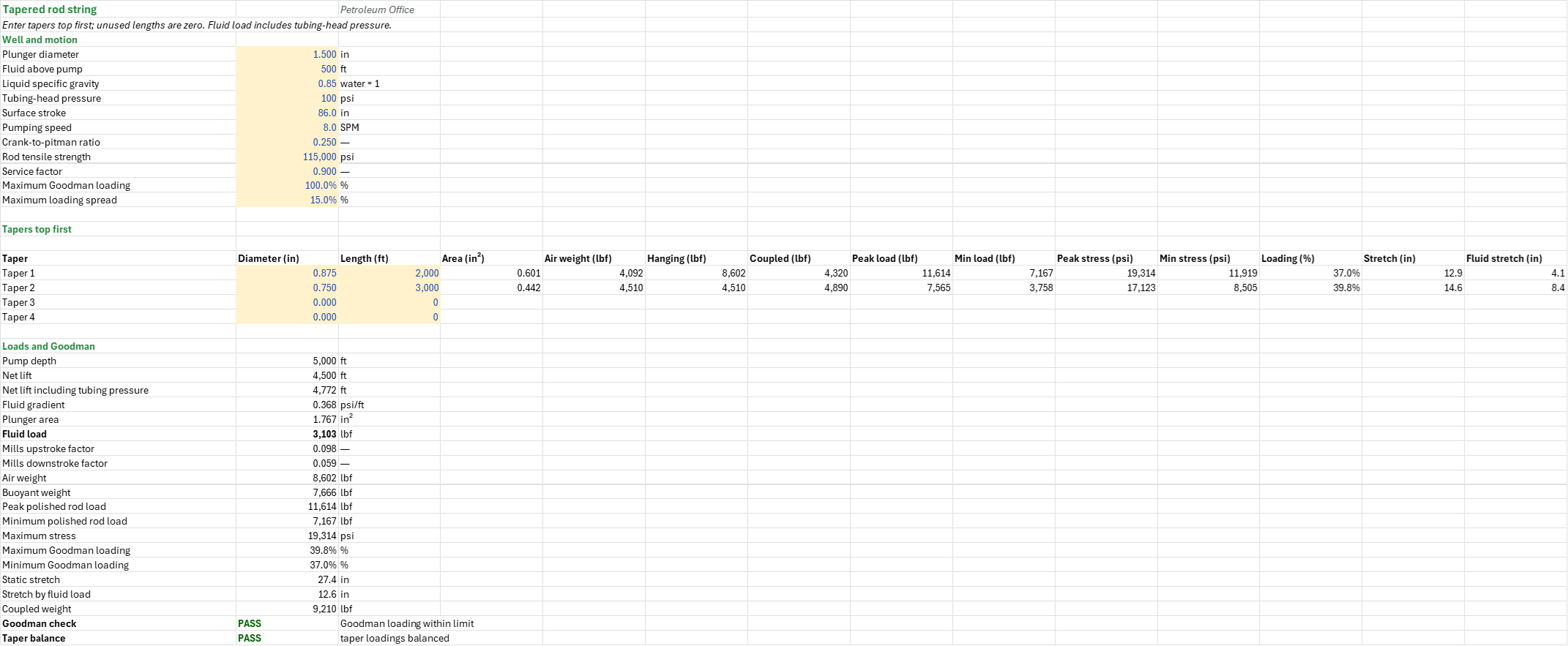
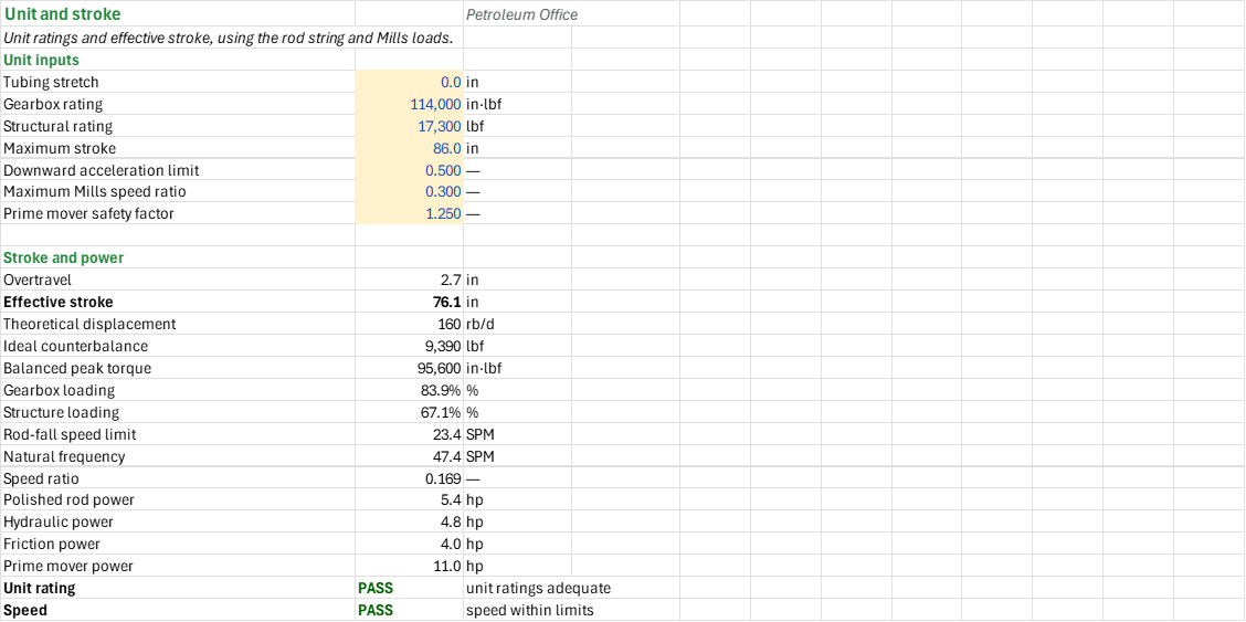
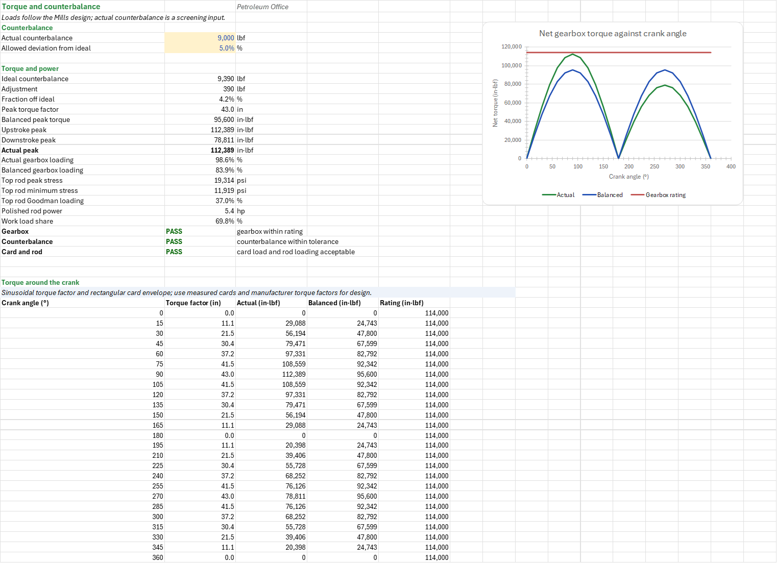
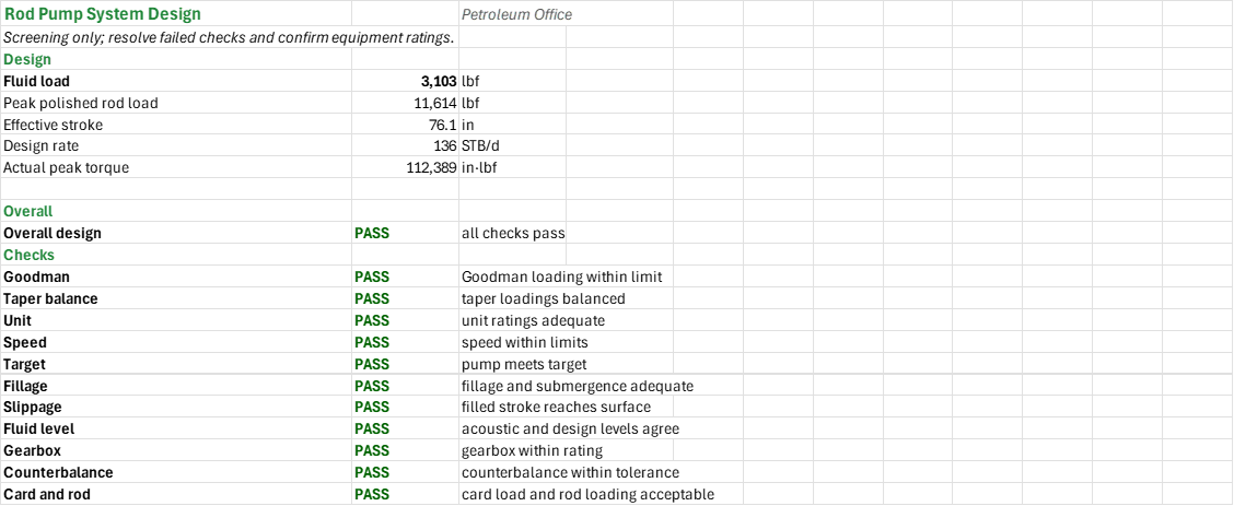
Example: A 1.5 inch plunger at 5,000 ft with 500 ft of submergence, 100 psig tubing-head pressure, 0.85 liquid specific gravity, and 2,000 ft of 7/8 inch over 3,000 ft of 3/4 inch grade D rods, on a conventional unit at 86 inches and 8 SPM. The net lift including surface pressure is about 4,772 ft and the fluid load 3,103 lbf. Mills gives about 11,614 lbf peak and 7,167 lbf minimum polished-rod load, and the most-loaded taper uses about 39.8% of its Goodman allowance. Rod stretch under fluid load is about 12.56 in and overtravel 2.66 in, giving a 76.1 in effective stroke and 159.7 rb/d theoretical displacement. The balanced peak torque is about 95,600 in-lbf, 83.9% of the gearbox rating, and the prime mover needs about 11.0 hp. At 85% design efficiency the pump delivers about 135.7 STB/d against the 130 STB/d target. The 7.2 s acoustic echo at 1,250 ft/s puts the fluid level at 4,500 ft, 500 ft above the pump. The ideal counterbalance is about 9,390 lbf; with 9,000 lbf actual counterbalance the peak torque is about 112,400 in-lbf against the 114,000 in-lbf rating.
Validity
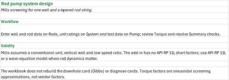
Mills assumes a conventional unit and a rigid string in a vertical well at a low speed ratio. The gas-free fluid gradient leaves out friction and rod buckling. The add-in has no function for the API RP 11L chart factors; use API RP 11L or a wave-equation model when the rods' elastic dynamics matter. The add-in has no functions for card reconstruction (Gibbs) or card diagnosis. The actual torque uses a sinusoidal factor and a rectangular card; confirm it against measured cards and the manufacturer's torque factors. Coupled weights need standard rod sizes. The acoustic reading is an independent measurement and must agree with the design submergence. The pump rate against plunger size and speed is not tabulated; recalculate the effective stroke when you change the plunger size. Alternatives: displacement directly from plunger diameter, API chart-factor loads, and power from a measured card area; none of them replaces checking the chosen method and its inputs.
References
- API RP 11BR, Recommended Practice for the Care and Handling of Sucker Rods (modified Goodman and service factors).
- API RP 11L, Recommended Practice for Design Calculations for Sucker Rod Pumping Systems.
- API Spec 11E, Specification for Pumping Units.
- Guo, B., Lyons, W.C. and Ghalambor, A. (2007), Petroleum Production Engineering: A Computer-Assisted Approach, chapter 12 (Mills loads and rod-fall speed).
- Economides, M.J., Hill, A.D. and Ehlig-Economides, C. (1994), Petroleum Production Systems, chapter 20 (net lift, displacement and effective stroke).
- McCoy, J.N., Podio, A.L. and Huddleston, K.L. (1988), "Acoustic Determination of Producing Bottomhole Pressure," SPE 14254 (acoustic level).
Inputs
| Input | Unit | Default | Name |
|---|---|---|---|
| Plunger diameter | in | 1.5 | RDR_Dp |
| Fluid above pump | ft | 500 | RDR_Hsub |
| Liquid specific gravity | — | 0.85 | RDR_SG |
| Tubing-head pressure | psig | 100 | RDR_Ptf |
| Surface stroke | in | 86 | RDR_S |
| Pumping speed | SPM | 8 | RDR_N |
| Crank-to-pitman ratio | — | 0.25 | RDR_CH |
| Taper diameter, tapers 1 to 4 (top first) | in | 0.875, 0.75, 0, 0 | RDR_DiaA to RDR_DiaD |
| Taper length, tapers 1 to 4 (unused lengths zero) | ft | 2000, 3000, 0, 0 | RDR_LenA to RDR_LenD |
| Rod tensile strength | psi | 115000 | RDR_T |
| Service factor | — | 0.9 | RDR_SF |
| Maximum Goodman loading | fraction | 1.0 | RDR_MaxLoading |
| Maximum loading spread | fraction | 0.15 | RDR_Balance |
| Tubing stretch | in | 0 | RDS_TubStretch |
| Gearbox rating | in-lbf | 114000 | RDS_Gearbox |
| Structural rating | lbf | 17300 | RDS_Structure |
| Maximum stroke | in | 86 | RDS_MaxStroke |
| Downward acceleration limit | — | 0.5 | RDS_Lacc |
| Maximum Mills speed ratio | — | 0.3 | RDS_NNoMax |
| Prime mover safety factor | — | 1.25 | RDS_Fs |
| Target rate | STB/d | 130 | RDP_Qt |
| Well test rate | STB/d | 125 | RDP_Qa |
| Card fillage | fraction | 0.9 | RDP_Fill |
| Design volumetric efficiency | fraction | 0.85 | RDP_Ev |
| Echo time | s | 7.2 | RDP_Echo |
| Acoustic velocity | ft/s | 1250 | RDP_Vac |
| Collars counted | — | 0 | RDP_Joints |
| Joint length | ft | 31.5 | RDP_JointLen |
| Minimum fillage | fraction | 0.85 | RDP_FillMin |
| Minimum submergence | ft | 200 | RDP_SubMin |
| Minimum filled stroke delivered | fraction | 0.85 | RDP_SlipMin |
| Actual counterbalance | lbf | 9000 | RDT_CBEa |
| Allowed deviation from ideal | fraction | 0.05 | RDT_CbeTol |
Sheets
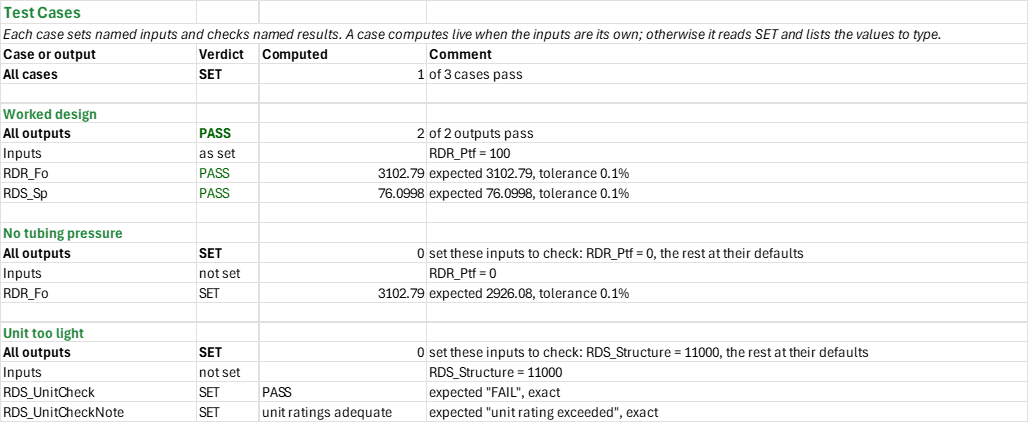
Guide— what the workbook screens, the order to work through its sheets, and what it leaves out.Rods— the well, motion and rod-grade inputs and the tapers top first; each taper's weight, Mills peak and minimum loads, stresses, Goodman loading and stretch; the pump depth, net lift, fluid load and polished-rod loads; the Goodman and taper-balance checks.System— the unit ratings and limits; overtravel, effective stroke and theoretical displacement; ideal counterbalance and balanced peak torque; gearbox and structure loading, rod-fall speed limit and speed ratio; polished-rod, hydraulic, friction and prime-mover power; the unit and speed checks.Pump— target rate, well test and acoustic shot; displacement, filled displacement, design rate and required speed; test efficiency and slippage; fluid level, acoustic submergence and submergence pressure; the rate, fillage, slippage and fluid-level checks.Torque— actual counterbalance against ideal, balanced and actual peak torque and gearbox loading, top-rod stresses and Goodman loading, and the net gearbox torque every 15 degrees around the crank.Summary— the design headlines and every check under one verdict.Test Cases— the worked example and other cases, with expected and computed results.
One chart: net gearbox torque against crank angle at the actual and the ideal counterbalance, with the gearbox rating.
Functions used
Names (139)
| Name | Refers to | Comment |
|---|---|---|
PO.RP.Fluidlevel.EchoLAMBDA |
=LAMBDA(t_echo, v_acoustic, joints, joint_len, pump_depth, output, IF(OR(t_echo<=0, pump_depth<=0, joints<0, AND(joints>0, joint_len<=0), AND(joints=0, v_acoustic<=0)), NA(), LET(level, IF(joints>0, joints*joint_len, v_acoustic*t_echo/2), IF(output="Level", level, IF(output="Submergence", pump_depth-level, IF(output="Velocity", 2*level/t_echo, NA())))))) |
Annulus fluid level from an acoustic shot: v·t/2, or joints × joint length when joints > 0; output "Level" (ft from surface), "Submergence" (pump depth − level, ft) or "Velocity" (implied, ft/s). |
PO.RP.Rod.TaperStressLAMBDA |
=LAMBDA(t_min, s_max, s_min, sf, output, IF(OR(t_min<=0, sf<=0, s_min<0, s_max<s_min), NA(), LET(sa, (t_min/4+0.5625*s_min)*sf, IF(output="Sa", sa, IF(output="Loading", IF(sa<=s_min, NA(), (s_max-s_min)/(sa-s_min)), IF(output="Margin", sa-s_max, NA())))))) |
API RP 11BR modified Goodman check of a rod taper, Sa = (T/4 + 0.5625·Smin)·SF; output "Sa" (psi), "Loading" ((Smax − Smin)/(Sa − Smin)) or "Margin" (Sa − Smax, psi). |
RDP_Cap |
Pump!$B$19 |
Design rate, STB/d |
RDP_Echo |
Pump!$B$8 |
Echo time, s |
RDP_Ev |
Pump!$B$7 |
Design volumetric efficiency, % |
RDP_EvTest |
Pump!$B$21 |
Test efficiency, % |
RDP_Fill |
Pump!$B$6 |
Card fillage, % |
RDP_FillCheck |
Pump!$B$28 |
Fillage verdict |
RDP_FillCheckNote |
Pump!$C$28 |
Fillage comment |
RDP_FillMin |
Pump!$B$12 |
Minimum fillage, % |
RDP_Inputs |
Pump!$B$4:$B$14 |
Target, well test and acoustic shot |
RDP_JointLen |
Pump!$B$11 |
Joint length, ft |
RDP_Joints |
Pump!$B$10 |
Collars counted |
RDP_Level |
Pump!$B$23 |
Fluid level, ft |
RDP_LevelCheck |
Pump!$B$30 |
Fluid level consistency verdict |
RDP_LevelCheckNote |
Pump!$C$30 |
Fluid level consistency comment |
RDP_Nreq |
Pump!$B$20 |
Required speed, SPM |
RDP_PD |
Pump!$B$17 |
Displacement, rb/d |
RDP_PDfill |
Pump!$B$18 |
Filled displacement, rb/d |
RDP_Psub |
Pump!$B$26 |
Submergence pressure, psi |
RDP_Qa |
Pump!$B$5 |
Well test rate, STB/d |
RDP_Qt |
Pump!$B$4 |
Target rate, STB/d |
RDP_RateCheck |
Pump!$B$27 |
Target rate verdict |
RDP_RateCheckNote |
Pump!$C$27 |
Target rate comment |
RDP_Results |
Pump!$B$17:$B$30 |
Displacement, efficiencies, acoustic level and checks |
RDP_Slip |
Pump!$B$22 |
Filled stroke reaching surface, % |
RDP_SlipCheck |
Pump!$B$29 |
Slippage verdict |
RDP_SlipCheckNote |
Pump!$C$29 |
Slippage comment |
RDP_SlipMin |
Pump!$B$14 |
Minimum filled stroke delivered, % |
RDP_Sub |
Pump!$B$24 |
Acoustic submergence, ft |
RDP_SubMin |
Pump!$B$13 |
Minimum submergence, ft |
RDP_Vac |
Pump!$B$9 |
Acoustic velocity, ft/s |
RDP_Vimp |
Pump!$B$25 |
Implied acoustic velocity, ft/s |
RDR_Ap |
Rods!$B$29 |
Plunger area, in² |
RDR_Balance |
Rods!$B$14 |
Maximum loading spread, % |
RDR_BalanceCheck |
Rods!$B$44 |
Taper balance verdict |
RDR_BalanceCheckNote |
Rods!$C$44 |
Taper balance comment |
RDR_CH |
Rods!$B$10 |
Crank-to-pitman ratio |
RDR_Check |
Rods!$B$43 |
Goodman check verdict |
RDR_CheckNote |
Rods!$C$43 |
Goodman check comment |
RDR_Depth |
Rods!$B$25 |
Pump depth, ft |
RDR_DiaA |
Rods!$B$19 |
Taper diameter, in |
RDR_DiaB |
Rods!$B$20 |
Taper diameter, in |
RDR_DiaC |
Rods!$B$21 |
Taper diameter, in |
RDR_DiaD |
Rods!$B$22 |
Taper diameter, in |
RDR_Dp |
Rods!$B$4 |
Plunger diameter, in |
RDR_F1 |
Rods!$B$31 |
Mills upstroke factor |
RDR_F2 |
Rods!$B$32 |
Mills downstroke factor |
RDR_Fo |
Rods!$B$30 |
Fluid load, lbf |
RDR_Grad |
Rods!$B$28 |
Fluid gradient, psi/ft |
RDR_Hsub |
Rods!$B$5 |
Fluid above pump, ft |
RDR_Inputs |
Rods!$B$4:$B$14 |
Well, motion and rod grade inputs |
RDR_LN |
Rods!$B$27 |
Net lift including tubing pressure, ft |
RDR_LenA |
Rods!$C$19 |
Taper length, ft |
RDR_LenB |
Rods!$C$20 |
Taper length, ft |
RDR_LenC |
Rods!$C$21 |
Taper length, ft |
RDR_LenD |
Rods!$C$22 |
Taper length, ft |
RDR_Loading |
Rods!$B$38 |
Maximum Goodman loading, % |
RDR_LoadingMin |
Rods!$B$39 |
Minimum Goodman loading, % |
RDR_MPRL |
Rods!$B$36 |
Minimum polished rod load, lbf |
RDR_MaxLoading |
Rods!$B$13 |
Maximum Goodman loading, % |
RDR_MaxStress |
Rods!$B$37 |
Maximum stress, psi |
RDR_N |
Rods!$B$9 |
Pumping speed, SPM |
RDR_NetLift |
Rods!$B$26 |
Net lift, ft |
RDR_PPRL |
Rods!$B$35 |
Peak polished rod load, lbf |
RDR_Ptf |
Rods!$B$7 |
Tubing-head pressure, psi |
RDR_Results |
Rods!$B$25:$B$44 |
Loads, stress, stretch and checks |
RDR_RodStretch |
Rods!$B$41 |
Stretch by fluid load, in |
RDR_S |
Rods!$B$8 |
Surface stroke, in |
RDR_SF |
Rods!$B$12 |
Service factor |
RDR_SG |
Rods!$B$6 |
Liquid specific gravity, water = 1 |
RDR_Stretch |
Rods!$B$40 |
Static stretch, in |
RDR_T |
Rods!$B$11 |
Rod tensile strength, psi |
RDR_Tapers |
Rods!$A$19:$N$22 |
Taper inputs, loads, stresses and stretch |
RDR_Wc |
Rods!$B$42 |
Coupled weight, lbf |
RDR_Wr |
Rods!$B$33 |
Air weight, lbf |
RDR_Wrf |
Rods!$B$34 |
Buoyant weight, lbf |
RDS_CBE |
System!$B$16 |
Ideal counterbalance, lbf |
RDS_Ep |
System!$B$13 |
Overtravel, in |
RDS_FHP |
System!$B$25 |
Friction power, hp |
RDS_Fs |
System!$B$10 |
Prime mover safety factor |
RDS_Gearbox |
System!$B$5 |
Gearbox rating, in·lbf |
RDS_GearboxLoad |
System!$B$18 |
Gearbox loading, % |
RDS_HHP |
System!$B$24 |
Hydraulic power, hp |
RDS_Inputs |
System!$B$4:$B$10 |
Unit ratings and limits |
RDS_Lacc |
System!$B$8 |
Downward acceleration limit |
RDS_MaxStroke |
System!$B$7 |
Maximum stroke, in |
RDS_NNo |
System!$B$22 |
Speed ratio |
RDS_NNoMax |
System!$B$9 |
Maximum Mills speed ratio |
RDS_Nmax |
System!$B$20 |
Rod-fall speed limit, SPM |
RDS_No |
System!$B$21 |
Natural frequency, SPM |
RDS_PD |
System!$B$15 |
Theoretical displacement, rb/d |
RDS_PMHP |
System!$B$26 |
Prime mover power, hp |
RDS_PRHP |
System!$B$23 |
Polished rod power, hp |
RDS_Results |
System!$B$13:$B$28 |
Stroke, unit loading, power and checks |
RDS_Sp |
System!$B$14 |
Effective stroke, in |
RDS_SpeedCheck |
System!$B$28 |
Speed verdict |
RDS_SpeedCheckNote |
System!$C$28 |
Speed comment |
RDS_Structure |
System!$B$6 |
Structural rating, lbf |
RDS_StructureLoad |
System!$B$19 |
Structure loading, % |
RDS_Tpeak |
System!$B$17 |
Balanced peak torque, in·lbf |
RDS_TubStretch |
System!$B$4 |
Tubing stretch, in |
RDS_UnitCheck |
System!$B$27 |
Unit rating verdict |
RDS_UnitCheckNote |
System!$C$27 |
Unit rating comment |
RDT_Adj |
Torque!$B$9 |
Adjustment, lbf |
RDT_CBEa |
Torque!$B$4 |
Actual counterbalance, lbf |
RDT_CBEi |
Torque!$B$8 |
Ideal counterbalance, lbf |
RDT_CardShare |
Torque!$B$22 |
Work load share, % |
RDT_CbeCheck |
Torque!$B$24 |
Counterbalance verdict |
RDT_CbeCheckNote |
Torque!$C$24 |
Counterbalance comment |
RDT_CbeTol |
Torque!$B$5 |
Allowed deviation from ideal, % |
RDT_Check |
Torque!$B$23 |
Gearbox verdict |
RDT_CheckNote |
Torque!$C$23 |
Gearbox comment |
RDT_Curve |
Torque!$A$31:$E$55 |
Torque every 15 degrees at actual and ideal counterbalance, and gearbox rating |
RDT_GearboxLoad |
Torque!$B$16 |
Actual gearbox loading, % |
RDT_GearboxLoadBal |
Torque!$B$17 |
Balanced gearbox loading, % |
RDT_Inputs |
Torque!$B$4:$B$5 |
Counterbalance and tolerance |
RDT_LoadCheck |
Torque!$B$25 |
Card and rod verdict |
RDT_LoadCheckNote |
Torque!$C$25 |
Card and rod comment |
RDT_Loading |
Torque!$B$20 |
Top rod Goodman loading, % |
RDT_OffBalance |
Torque!$B$10 |
Fraction off ideal, % |
RDT_PRHP |
Torque!$B$21 |
Polished rod power, hp |
RDT_Results |
Torque!$B$8:$B$25 |
Counterbalance, torque and checks |
RDT_Smax |
Torque!$B$18 |
Top rod peak stress, psi |
RDT_Smin |
Torque!$B$19 |
Top rod minimum stress, psi |
RDT_TF |
Torque!$B$11 |
Peak torque factor, in |
RDT_Tbal |
Torque!$B$12 |
Balanced peak torque, in·lbf |
RDT_Tdown |
Torque!$B$14 |
Downstroke peak, in·lbf |
RDT_Tpeak |
Torque!$B$15 |
Actual peak, in·lbf |
RDT_Tup |
Torque!$B$13 |
Upstroke peak, in·lbf |
RDX_Cap |
Summary!$B$7 |
Design rate, STB/d |
RDX_Checks |
Summary!$B$13:$B$23 |
All checks |
RDX_Fo |
Summary!$B$4 |
Fluid load, lbf |
RDX_Overall |
Summary!$B$11 |
Overall design verdict |
RDX_OverallNote |
Summary!$C$11 |
Overall design comment |
RDX_PPRL |
Summary!$B$5 |
Peak polished rod load, lbf |
RDX_Results |
Summary!$B$4:$B$11 |
Design headlines and overall verdict |
RDX_Sp |
Summary!$B$6 |
Effective stroke, in |
RDX_Tpeak |
Summary!$B$8 |
Actual peak torque, in·lbf |
Details
| Opens in | Needs the Petroleum Office add-in: its PO functions show #NAME? without it once Excel recalculates. Needs Microsoft 365 or Excel 2024: it uses functions Excel 2016 doesn't have, such as named LAMBDAs, which show #NAME? there. |
| File | RodPumpDesign.xlsx, 38 KB |
| Category | Production |
| For agents and tools | Descriptor (.md) |