Gas-Lift Field Optimisation

Description
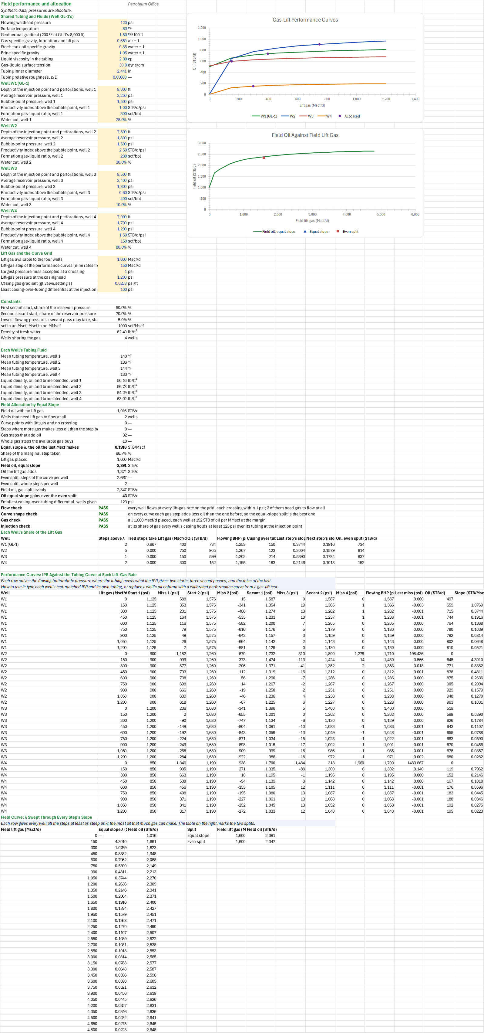
How should a limited lift-gas supply be split between wells to make the most oil? You enter the shared tubing and fluid data, each of four wells' depth, reservoir pressure, bubble point, productivity index, gas-liquid ratio and water cut, and the gas available. You read off each well's lift gas and oil by equal marginal slope, the field oil against no lift gas and an even split, and the first well's injection depth and valve differential. Field units, pressures absolute; the PO add-in is needed.
How to use it: The four wells are synthetic; replace every example with measured, test-matched field data. Enter the shared tubing and fluid inputs, the four reservoir and depth cases, the gas available, the grid step, the crossing tolerance, the casing gradient and the differential on the Allocation sheet. The Injection sheet takes W1's allocated gas and the same conditions; the minimum acceptable injection-depth fraction is an editable assumption there. Review the flow, curve-shape, gas and injection checks on the Summary.
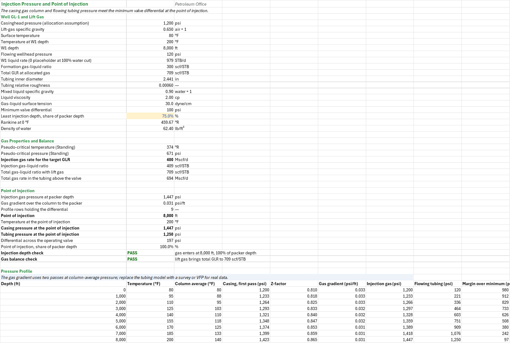
Method: For each well, nine gas-rate points are computed with a composite Vogel IPR and Hagedorn-Brown tubing, with two starting pressures and three bounded secant passes. Piecewise-linear marginal oil slopes allocate gas by equal slope. Tied marginal steps are taken deterministically in well order, with successive tied steps on a well taken in curve order. The result includes zero-gas and even-split comparisons. W1's allocated oil and water cut give its liquid rate; its allocated gas gives the total GLR for a two-pass static gas column and tubing profile that locate its injection point.
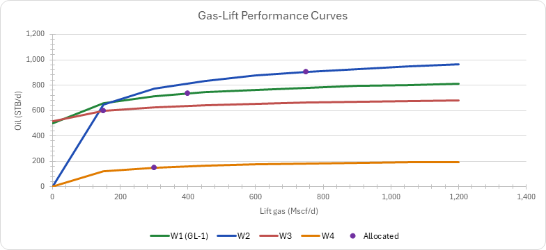
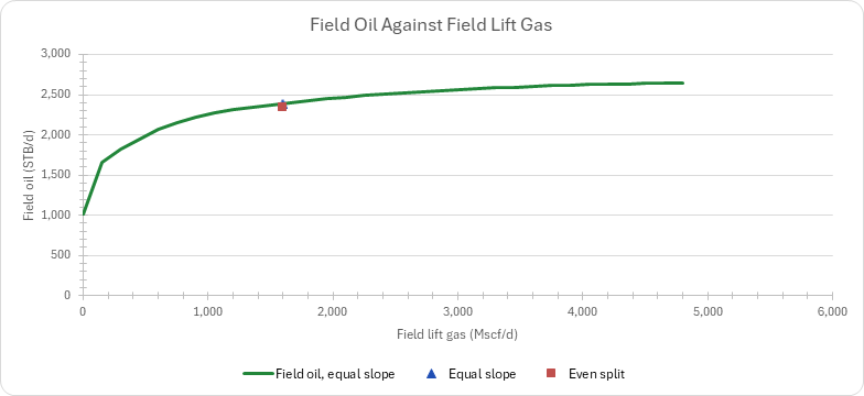
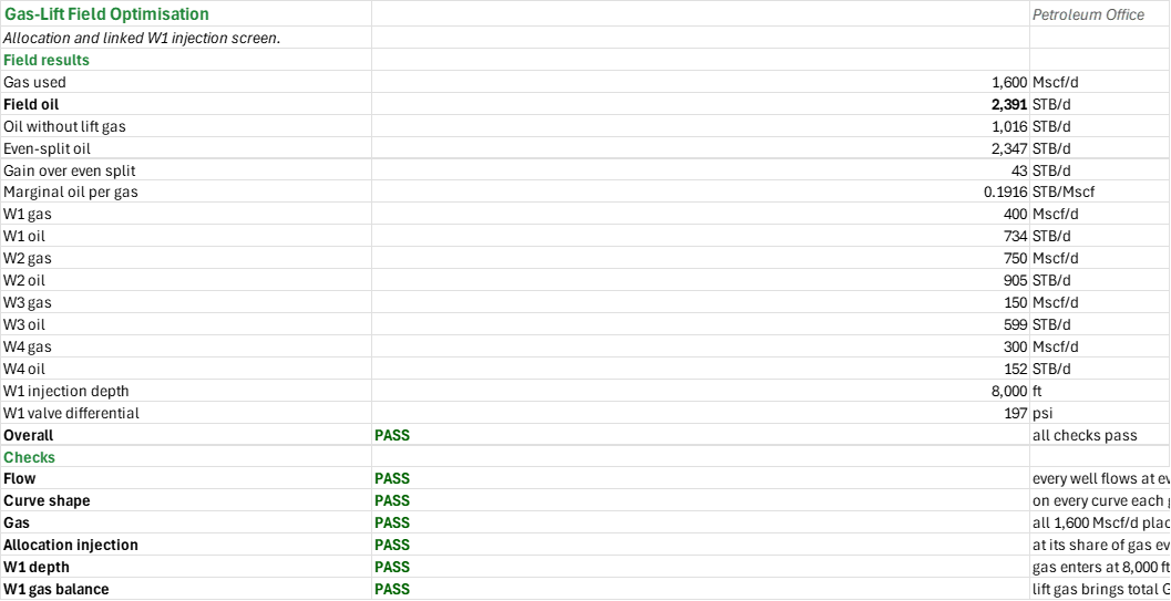
Example: The synthetic 1,600 Mscf/d case is approximately 400, 750, 150 and 300 Mscf/d across W1-W4, producing approximately 2,391 STB/d versus 2,347 STB/d for an even split. These rounded figures are indicative; use the recalculated unrounded workbook values.
Validity
The example is not a field design. Wells share tubing and fluid assumptions. Equal slope is optimal only for the sampled piecewise-linear curves when marginal returns do not increase; warnings identify departures. Allocation assumes injection at the bottom and a constant casing gas gradient. The separate W1 profile can find a shallower injection point and assumes all gas is present throughout the tubing; neither calculation is a segmented gas-lift traverse. Kickoff pressure of 1,200 psia is an assumed operating casinghead pressure for the linked case, not the independent GL-1 example's 1,000 psia. A zero-flow W1 has no pressure profile. At 100% water cut (or higher) W1 liquid rate cannot be inferred from oil; the zero shown in the liquid-rate cell is only a calculation placeholder, and the W1 checks fail rather than claim no liquid flow. Validate correlations and pressure limits against field surveys and vendor specifications.
References
- Kanu, E.P., Mach, J. and Brown, K.E. (1981). Economic Approach to Oil Production and Gas Allocation in Continuous Gas Lift. JPT 33(10), 1887-1892.
- Brown, K.E. (1980). The Technology of Artificial Lift Methods, Vol. 2a. PennWell.
- Takacs, G. (2005). Gas Lift Manual. PennWell.
- American Petroleum Institute. API RP 11V6, Recommended Practice for Design of Continuous Flow Gas Lift Installations Using Injection Pressure Operated Valves.
- Vogel, J.V. (1968). Inflow Performance Relationships for Solution-Gas Drive Wells. JPT 20(1), 83-92.
- Hagedorn, A.R. and Brown, K.E. (1965). Experimental Study of Pressure Gradients Occurring During Continuous Two-Phase Flow in Small-Diameter Vertical Conduits. JPT 17(4), 475-484.
Inputs
| Input | Unit | Default | Name |
|---|---|---|---|
| Flowing wellhead pressure | psia | 120 | FOA_Pwh |
| Surface temperature | °F | 80 | FOA_Ts |
| Geothermal gradient (200 °F at GL-1's 8,000 ft) | °F/100 ft | 1.5 | FOA_Tgrad |
| Gas specific gravity, formation and lift gas | — | 0.65 | FOA_SGg |
| Stock-tank oil specific gravity | — | 0.85 | FOA_SGo |
| Brine specific gravity | — | 1.05 | FOA_SGw |
| Liquid viscosity in the tubing | cP | 2 | FOA_UL |
| Gas-liquid surface tension | dyne/cm | 30 | FOA_IFT |
| Tubing inner diameter | in | 2.441 | FOA_ID |
| Tubing relative roughness, ε/D | — | 0.0006 | FOA_Rough |
| Depth of the injection point and perforations, wells 1 to 4 | ft | 8,000, 7,500, 8,500, 7,000 | FOA_D1 … FOA_D4 |
| Average reservoir pressure, wells 1 to 4 | psia | 2,250, 1,800, 2,400, 1,700 | FOA_Pr1 … FOA_Pr4 |
| Bubble-point pressure, wells 1 to 4 | psia | 1,500, 1,500, 1,800, 1,200 | FOA_Pb1 … FOA_Pb4 |
| Productivity index above the bubble point, wells 1 to 4 | STB/d/psi | 1.0, 2.5, 0.6, 1.5 | FOA_J1 … FOA_J4 |
| Formation gas-liquid ratio, wells 1 to 4 | scf/STB | 300, 200, 400, 150 | FOA_GLR1 … FOA_GLR4 |
| Water cut, wells 1 to 4 | % | 25, 30, 10, 80 | FOA_WC1 … FOA_WC4 |
| Lift gas available to the four wells | Mscf/d | 1,600 | FOA_Gav |
| Lift-gas step of the performance curves (nine rates from 0) | Mscf/d | 150 | FOA_Step |
| Largest pressure miss accepted at a crossing | psi | 1 | FOA_Tol |
| Lift-gas pressure at the casinghead | psia | 1,200 | FOA_Pinj |
| Casing gas gradient | psi/ft | 0.0253 | FOA_Gg |
| Least casing-over-tubing differential at the injection point | psi | 100 | FOA_dPmin |
| Least injection depth, share of packer depth (Injection) | % | 75 | FOI_PoiMin |
Sheets
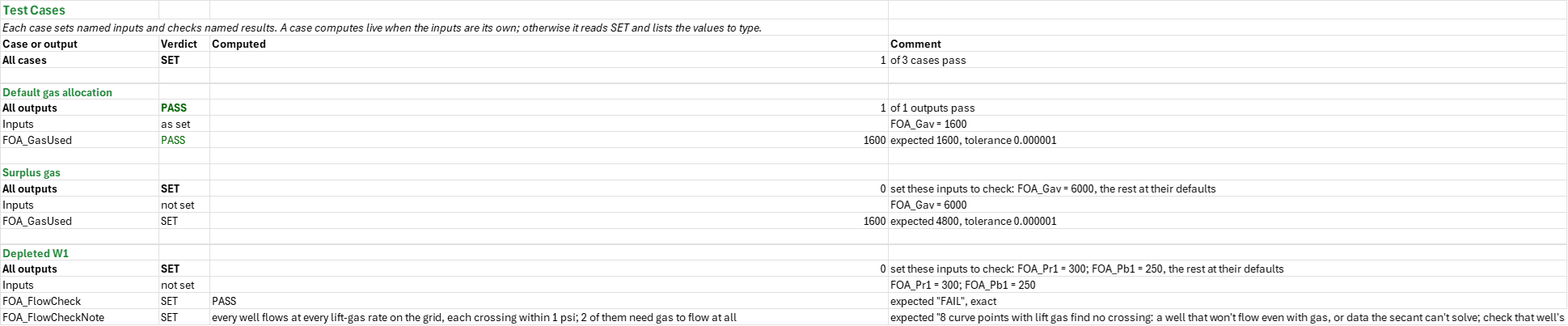
Guide— four synthetic wells sharing a limited lift-gas supply, the data to use and the assumptions of the allocation and the W1 profile.Allocation— the shared tubing and fluids and the four wells; each well's performance curve, its IPR against the tubing curve at nine lift-gas rates; the equal-slope field allocation and each well's share of the gas against an even split; and the field curve with λ swept through every step's slope, charted.Injection— W1 at its allocated gas: the casing gas column and the flowing tubing pressure meeting the minimum valve differential at the point of injection, and the pressure profile.Summary— gas used, field oil, oil without lift gas, even-split oil and the gain over it, the marginal oil per gas, each well's gas and oil, W1's injection depth and valve differential, and every check under one verdict.Test Cases— the worked example and other cases, with expected and computed results.
Two charts: the four wells' gas-lift performance curves, and field oil against field lift gas.
Functions used
Names (157)
| Name | Refers to | Comment |
|---|---|---|
FOA_Allocation |
Allocation!$A$90:$J$93 |
Each well's steps above the marginal slope and tied steps taken in well order, its lift gas, oil, flowing pressure and casing margin, the slopes either side of its share, and its oil on an even split |
FOA_Bends |
Allocation!$B$71 |
Steps where more gas makes less oil than the step before |
FOA_D1 |
Allocation!$B$15 |
Depth of the injection point and perforations, well 1, ft |
FOA_D2 |
Allocation!$B$22 |
Depth of the injection point and perforations, well 2, ft |
FOA_D3 |
Allocation!$B$29 |
Depth of the injection point and perforations, well 3, ft |
FOA_D4 |
Allocation!$B$36 |
Depth of the injection point and perforations, well 4, ft |
FOA_Dead |
Allocation!$B$70 |
Curve points with lift gas and no crossing |
FOA_Fa |
Allocation!$B$51 |
First secant start, share of the reservoir pressure, % |
FOA_Fb |
Allocation!$B$52 |
Second secant start, share of the reservoir pressure, % |
FOA_FieldSweep |
Allocation!$A$138:$C$170 |
The field's lift gas in steps, the equal slope λ that places it, and the most oil it makes |
FOA_FlowCheck |
Allocation!$B$84 |
Flow check verdict |
FOA_FlowCheckNote |
Allocation!$C$84 |
Flow check comment |
FOA_Fmin |
Allocation!$B$53 |
Lowest flowing pressure a secant pass may take, share of Pr, % |
FOA_Frac |
Allocation!$B$75 |
Share of the marginal step taken, % |
FOA_GLR1 |
Allocation!$B$19 |
Formation gas-liquid ratio, well 1, scf/bbl |
FOA_GLR2 |
Allocation!$B$26 |
Formation gas-liquid ratio, well 2, scf/bbl |
FOA_GLR3 |
Allocation!$B$33 |
Formation gas-liquid ratio, well 3, scf/bbl |
FOA_GLR4 |
Allocation!$B$40 |
Formation gas-liquid ratio, well 4, scf/bbl |
FOA_Gain |
Allocation!$B$78 |
Oil the lift gas adds, STB/d |
FOA_GasCheck |
Allocation!$B$86 |
Gas check verdict |
FOA_GasCheckNote |
Allocation!$C$86 |
Gas check comment |
FOA_GasUsed |
Allocation!$B$76 |
Lift gas placed, Mscf/d |
FOA_Gav |
Allocation!$B$43 |
Lift gas available to the four wells, Mscf/d |
FOA_Gg |
Allocation!$B$47 |
Casing gas gradient (gl.valve.setting's), psi/ft |
FOA_ID |
Allocation!$B$12 |
Tubing inner diameter, in |
FOA_IFT |
Allocation!$B$11 |
Gas-liquid surface tension, dyne/cm |
FOA_Ieven |
Allocation!$B$80 |
Even split, whole steps per well |
FOA_InjectionCheck |
Allocation!$B$87 |
Injection check verdict |
FOA_InjectionCheckNote |
Allocation!$C$87 |
Injection check comment |
FOA_Inputs |
Allocation!$B$4:$B$48 |
Shared tubing, fluids and temperatures, each well's depth, reservoir and bubble-point pressures, J, GLR and water cut, the lift gas available, the curve grid's step, the crossing tolerance, and the casing pressure and differential at the injection point |
FOA_J1 |
Allocation!$B$18 |
Productivity index above the bubble point, well 1, STB/d/psi |
FOA_J2 |
Allocation!$B$25 |
Productivity index above the bubble point, well 2, STB/d/psi |
FOA_J3 |
Allocation!$B$32 |
Productivity index above the bubble point, well 3, STB/d/psi |
FOA_J4 |
Allocation!$B$39 |
Productivity index above the bubble point, well 4, STB/d/psi |
FOA_Kick |
Allocation!$B$69 |
Wells that need lift gas to flow at all, wells |
FOA_Kilo |
Allocation!$B$54 |
scf in an Mscf, Mscf in an MMscf, scf/Mscf |
FOA_Lambda |
Allocation!$B$74 |
Equal slope λ, the oil the last Mscf makes, STB/Mscf |
FOA_MarginMin |
Allocation!$B$83 |
Smallest casing-over-tubing differential, wells given gas, psi |
FOA_Nfull |
Allocation!$B$73 |
Whole gas steps the available gas buys |
FOA_Npos |
Allocation!$B$72 |
Gas steps that add oil |
FOA_Nw |
Allocation!$B$56 |
Wells sharing the gas, wells |
FOA_Pb1 |
Allocation!$B$17 |
Bubble-point pressure, well 1, psi |
FOA_Pb2 |
Allocation!$B$24 |
Bubble-point pressure, well 2, psi |
FOA_Pb3 |
Allocation!$B$31 |
Bubble-point pressure, well 3, psi |
FOA_Pb4 |
Allocation!$B$38 |
Bubble-point pressure, well 4, psi |
FOA_Performance |
Allocation!$A$99:$N$134 |
Each well at nine lift-gas rates: two starting pressures and three secant passes on the flowing bottomhole pressure, each pass's miss, the oil at the solved pressure, and the slope from the rate before |
FOA_Pinj |
Allocation!$B$46 |
Lift-gas pressure at the casinghead, psi |
FOA_Pr1 |
Allocation!$B$16 |
Average reservoir pressure, well 1, psi |
FOA_Pr2 |
Allocation!$B$23 |
Average reservoir pressure, well 2, psi |
FOA_Pr3 |
Allocation!$B$30 |
Average reservoir pressure, well 3, psi |
FOA_Pr4 |
Allocation!$B$37 |
Average reservoir pressure, well 4, psi |
FOA_Pwf1 |
Allocation!$F$90 |
Flowing bottomhole pressure of well 1 at its allocated gas, psia |
FOA_Pwf2 |
Allocation!$F$91 |
Flowing bottomhole pressure of well 2 at its allocated gas, psia |
FOA_Pwf3 |
Allocation!$F$92 |
Flowing bottomhole pressure of well 3 at its allocated gas, psia |
FOA_Pwf4 |
Allocation!$F$93 |
Flowing bottomhole pressure of well 4 at its allocated gas, psia |
FOA_PwfStep1 |
Allocation!$K$100 |
Flowing bottomhole pressure of well 1 at one gas step, psia |
FOA_Pwh |
Allocation!$B$4 |
Flowing wellhead pressure, psi |
FOA_Qgi1 |
Allocation!$D$90 |
Lift gas allocated to well 1, Mscf/d |
FOA_Qgi2 |
Allocation!$D$91 |
Lift gas allocated to well 2, Mscf/d |
FOA_Qgi3 |
Allocation!$D$92 |
Lift gas allocated to well 3, Mscf/d |
FOA_Qgi4 |
Allocation!$D$93 |
Lift gas allocated to well 4, Mscf/d |
FOA_Qo0 |
Allocation!$B$68 |
Field oil with no lift gas, STB/d |
FOA_Qo1 |
Allocation!$E$90 |
Oil rate of well 1 at its allocated gas, STB/d |
FOA_Qo2 |
Allocation!$E$91 |
Oil rate of well 2 at its allocated gas, STB/d |
FOA_Qo3 |
Allocation!$E$92 |
Oil rate of well 3 at its allocated gas, STB/d |
FOA_Qo4 |
Allocation!$E$93 |
Oil rate of well 4 at its allocated gas, STB/d |
FOA_QoEven |
Allocation!$B$81 |
Field oil, gas split evenly, STB/d |
FOA_QoField |
Allocation!$B$77 |
Field oil, equal slope, STB/d |
FOA_QoStep1 |
Allocation!$M$100 |
Oil rate of well 1 at one gas step, STB/d |
FOA_Results |
Allocation!$B$59:$B$87 |
Each well's mean temperature and liquid density, the field oil with no gas, the equal slope and the gas placed, the field oil and its gain over an even split, and the flow, shape, gas and injection checks |
FOA_RhoL1 |
Allocation!$B$63 |
Liquid density, oil and brine blended, well 1, lb/ft³ |
FOA_RhoL2 |
Allocation!$B$64 |
Liquid density, oil and brine blended, well 2, lb/ft³ |
FOA_RhoL3 |
Allocation!$B$65 |
Liquid density, oil and brine blended, well 3, lb/ft³ |
FOA_RhoL4 |
Allocation!$B$66 |
Liquid density, oil and brine blended, well 4, lb/ft³ |
FOA_RhoW |
Allocation!$B$55 |
Density of fresh water, lb/ft³ |
FOA_Rough |
Allocation!$B$13 |
Tubing relative roughness, ε/D |
FOA_SGg |
Allocation!$B$7 |
Gas specific gravity, formation and lift gas, air = 1 |
FOA_SGo |
Allocation!$B$8 |
Stock-tank oil specific gravity, water = 1 |
FOA_SGw |
Allocation!$B$9 |
Brine specific gravity, water = 1 |
FOA_ShapeCheck |
Allocation!$B$85 |
Curve shape check verdict |
FOA_ShapeCheckNote |
Allocation!$C$85 |
Curve shape check comment |
FOA_Step |
Allocation!$B$44 |
Lift-gas step of the performance curves (nine rates from 0), Mscf/d |
FOA_Tgrad |
Allocation!$B$6 |
Geothermal gradient (200 °F at GL-1's 8,000 ft), °F/100 ft |
FOA_Tm1 |
Allocation!$B$59 |
Mean tubing temperature, well 1, °F |
FOA_Tm2 |
Allocation!$B$60 |
Mean tubing temperature, well 2, °F |
FOA_Tm3 |
Allocation!$B$61 |
Mean tubing temperature, well 3, °F |
FOA_Tm4 |
Allocation!$B$62 |
Mean tubing temperature, well 4, °F |
FOA_Tol |
Allocation!$B$45 |
Largest pressure miss accepted at a crossing, psi |
FOA_Ts |
Allocation!$B$5 |
Surface temperature, °F |
FOA_UL |
Allocation!$B$10 |
Liquid viscosity in the tubing, cp |
FOA_Uplift |
Allocation!$B$82 |
Oil equal slope gains over the even split, STB/d |
FOA_WC1 |
Allocation!$B$20 |
Water cut, well 1, % |
FOA_WC2 |
Allocation!$B$27 |
Water cut, well 2, % |
FOA_WC3 |
Allocation!$B$34 |
Water cut, well 3, % |
FOA_WC4 |
Allocation!$B$41 |
Water cut, well 4, % |
FOA_Xeven |
Allocation!$B$79 |
Even split, steps of the curve per well |
FOA_dPmin |
Allocation!$B$48 |
Least casing-over-tubing differential at the injection point, psi |
FOI_BalanceCheck |
Injection!$B$42 |
Gas balance check verdict |
FOI_BalanceCheckNote |
Injection!$C$42 |
Gas balance check comment |
FOI_DepthCheck |
Injection!$B$41 |
Injection depth check verdict |
FOI_DepthCheckNote |
Injection!$C$41 |
Injection depth check comment |
FOI_Dpk |
Injection!$B$8 |
W1 depth, ft |
FOI_GLRf |
Injection!$B$11 |
Formation gas-liquid ratio, scf/STB |
FOI_GLRi |
Injection!$B$27 |
Injection gas-liquid ratio, scf/STB |
FOI_GLRt |
Injection!$B$12 |
Total GLR at allocated gas, scf/STB |
FOI_GLRtot |
Injection!$B$28 |
Total gas-liquid ratio with lift gas, scf/STB |
FOI_Gbot |
Injection!$B$33 |
Gas gradient over the column to the packer, psi/ft |
FOI_ID |
Injection!$B$13 |
Tubing inner diameter, in |
FOI_IFT |
Injection!$B$17 |
Gas-liquid surface tension, dyne/cm |
FOI_Inputs |
Injection!$B$4:$B$19 |
Injection pressure, gas, well, tubing, fluid and minimum differential inputs |
FOI_POI |
Injection!$B$35 |
Point of injection, ft |
FOI_Pbot |
Injection!$B$32 |
Injection gas pressure at packer depth, psi |
FOI_PcPOI |
Injection!$B$37 |
Casing pressure at the point of injection, psi |
FOI_PoiMin |
Injection!$B$19 |
Least injection depth, share of packer depth, % |
FOI_PoiShare |
Injection!$B$40 |
Point of injection, share of packer depth, % |
FOI_Ppc |
Injection!$B$25 |
Pseudo-critical pressure (Standing), psi |
FOI_PressureData |
Injection!$A$47:$I$55 |
Depth, temperature, two-pass casing gas column, flowing tubing pressure and margin |
FOI_Ps |
Injection!$B$4 |
Casinghead pressure (allocation assumption), psi |
FOI_PtPOI |
Injection!$B$38 |
Tubing pressure at the point of injection, psi |
FOI_Pwh |
Injection!$B$9 |
Flowing wellhead pressure, psi |
FOI_Qgi |
Injection!$B$26 |
Injection gas rate for the target GLR, Mscf/d |
FOI_Qgt |
Injection!$B$29 |
Total gas rate in the tubing above the valve, Mscf/d |
FOI_Ql |
Injection!$B$10 |
W1 liquid rate (0 placeholder at 100% water cut), STB/d |
FOI_R0 |
Injection!$B$20 |
Rankine at 0 °F, °R |
FOI_Results |
Injection!$B$24:$B$42 |
Gas properties, gas balance, injection depth and pressures, and checks |
FOI_RhoW |
Injection!$B$21 |
Density of water, lb/ft³ |
FOI_Rough |
Injection!$B$14 |
Tubing relative roughness |
FOI_Rows |
Injection!$B$34 |
Profile rows holding the differential |
FOI_SG |
Injection!$B$5 |
Lift-gas specific gravity, air = 1 |
FOI_SGl |
Injection!$B$15 |
Mixed liquid specific gravity, water = 1 |
FOI_TPOI |
Injection!$B$36 |
Temperature at the point of injection, °F |
FOI_Tb |
Injection!$B$7 |
Temperature at W1 depth, °F |
FOI_Tpc |
Injection!$B$24 |
Pseudo-critical temperature (Standing), °R |
FOI_Ts |
Injection!$B$6 |
Surface temperature, °F |
FOI_Ul |
Injection!$B$16 |
Liquid viscosity, cp |
FOI_dPmin |
Injection!$B$18 |
Minimum valve differential, psi |
FOI_dPv |
Injection!$B$39 |
Differential across the operating valve, psi |
FOX_Checks |
Summary!$B$22:$B$27 |
Analysis checks |
FOX_GasUsed |
Summary!$B$4 |
Gas used, Mscf/d |
FOX_Lambda |
Summary!$B$9 |
Marginal oil per gas, STB/Mscf |
FOX_Overall |
Summary!$B$20 |
Overall verdict |
FOX_OverallNote |
Summary!$C$20 |
Overall comment |
FOX_POI |
Summary!$B$18 |
W1 injection depth, ft |
FOX_Qgi1 |
Summary!$B$10 |
W1 gas, Mscf/d |
FOX_Qgi2 |
Summary!$B$12 |
W2 gas, Mscf/d |
FOX_Qgi3 |
Summary!$B$14 |
W3 gas, Mscf/d |
FOX_Qgi4 |
Summary!$B$16 |
W4 gas, Mscf/d |
FOX_Qo0 |
Summary!$B$6 |
Oil without lift gas, STB/d |
FOX_Qo1 |
Summary!$B$11 |
W1 oil, STB/d |
FOX_Qo2 |
Summary!$B$13 |
W2 oil, STB/d |
FOX_Qo3 |
Summary!$B$15 |
W3 oil, STB/d |
FOX_Qo4 |
Summary!$B$17 |
W4 oil, STB/d |
FOX_QoEven |
Summary!$B$7 |
Even-split oil, STB/d |
FOX_QoField |
Summary!$B$5 |
Field oil, STB/d |
FOX_Results |
Summary!$B$4:$B$20 |
Field allocation, W1 injection and overall verdict |
FOX_Uplift |
Summary!$B$8 |
Gain over even split, STB/d |
FOX_dPv |
Summary!$B$19 |
W1 valve differential, psi |
Details
| Opens in | Needs the Petroleum Office add-in: its PO functions show #NAME? without it once Excel recalculates. |
| File | GasLiftOptimisation.xlsx, 62 KB |
| Category | Production |
| For agents and tools | Descriptor (.md) |