Continuous Gas-Lift Design
Description
How much lift gas does this well need, how deep can it be injected, and where do the unloading valves go? You enter the injection pressure, lift gas, well, tubing and fluid data, the kickoff and valve data, and the reservoir pressure and productivity. You read off the injection gas rate and depth, the unloading mandrels with their test-rack settings, the operating port and its throughput, and the nodal operating point. Field units, pressures absolute; the PO add-in is needed.
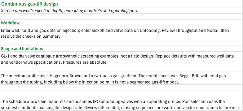
How to use it: GL-1 and the valve port list are synthetic examples, not field measurements or vendor specifications. Enter the well, fluid and gas data on the Injection sheet and the kickoff and valve data on the Unloading sheet, replacing the defaults with measured well tests, pressure and temperature surveys, fluid properties and verified vendor specifications. Replace the synthetic productivity index on the Nodal sheet with a well test. Review Throughput and Nodal, then resolve the checks on the Summary.
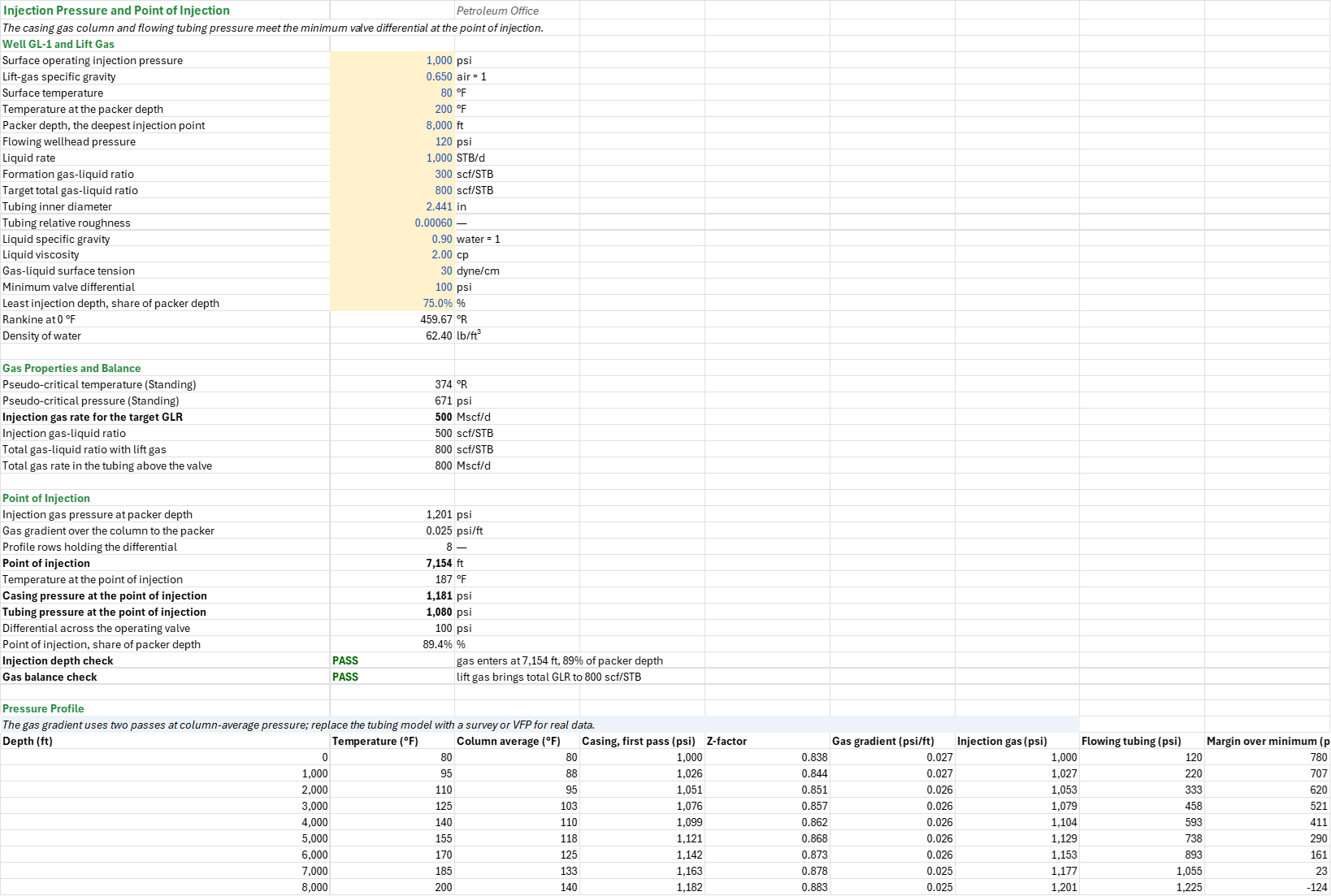
Method: Injection calculates the gas needed to reach the target GLR, a two-pass static gas column and a Hagedorn-Brown flowing tubing profile, and interpolates the deepest point meeting the minimum valve pressure differential. Unloading places IPO mandrels on a kill-fluid line and a straight transfer line, chooses the smallest listed port with adequate Thornhill-Craver capacity, and calculates valve dome, closing and test-rack pressures. Throughput checks critical flow at the selected port. Nodal intersects a composite Darcy/Vogel oil IPR and a Beggs-Brill vertical tubing curve on finite rate grids. Summary collects the results and the checks.
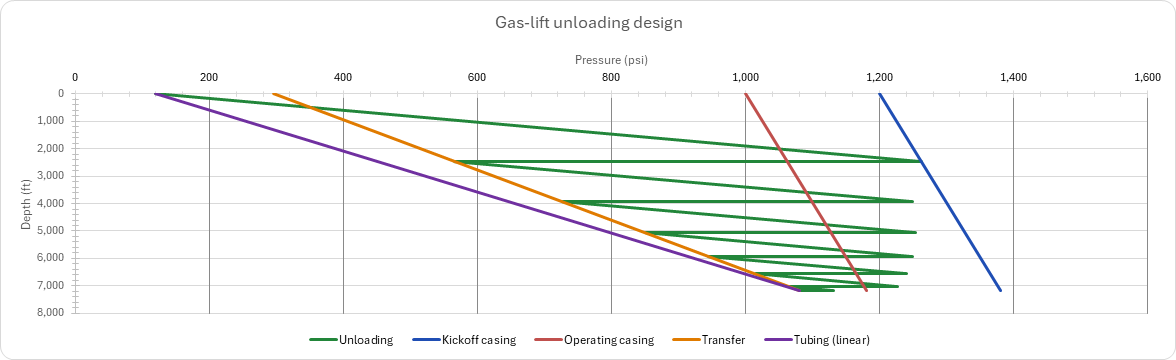
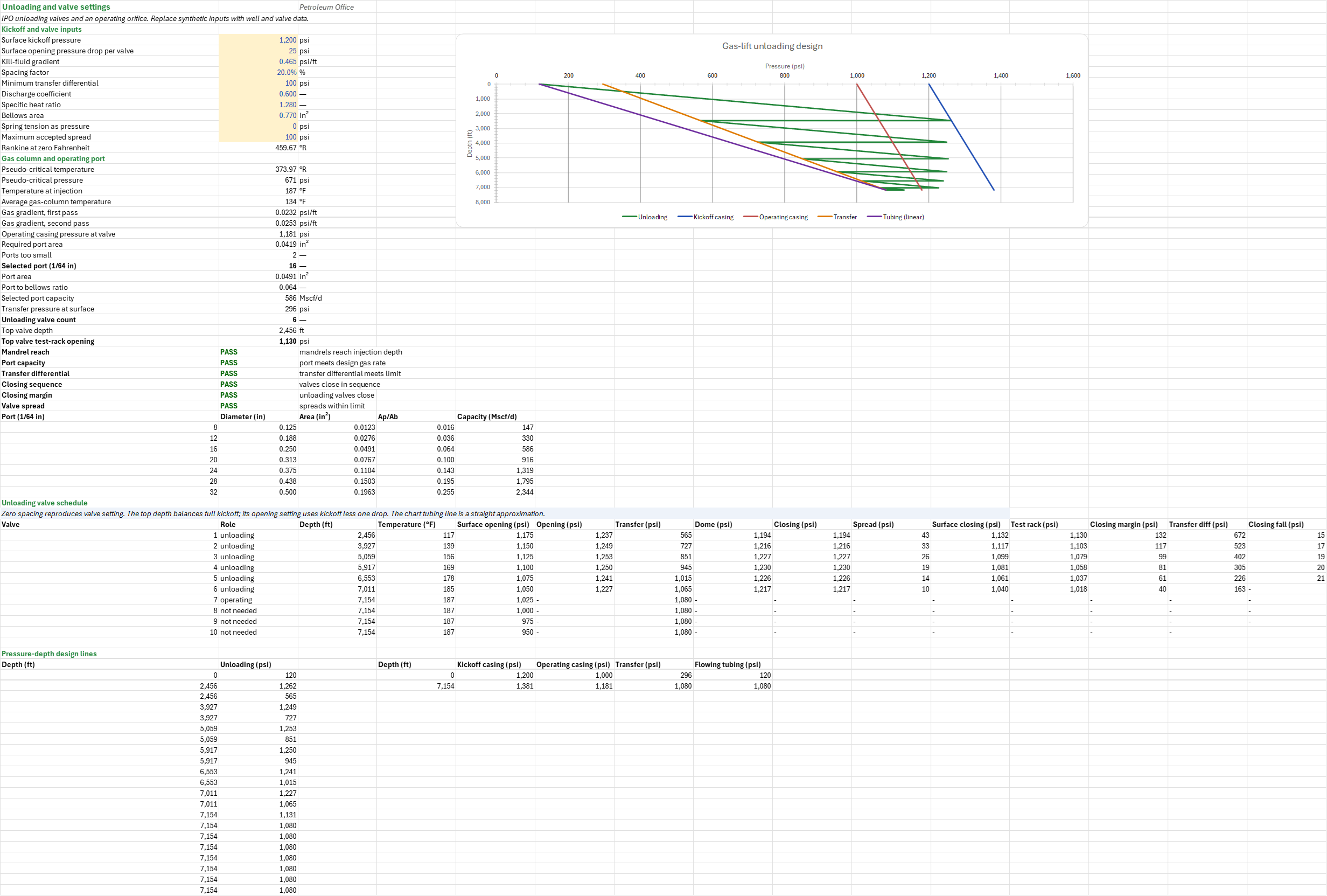
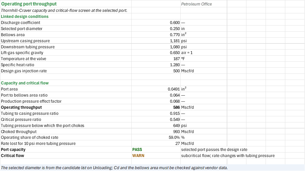
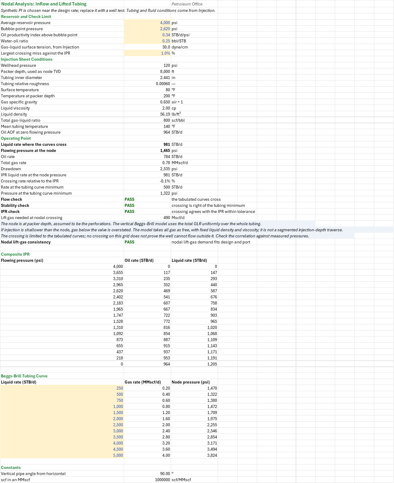
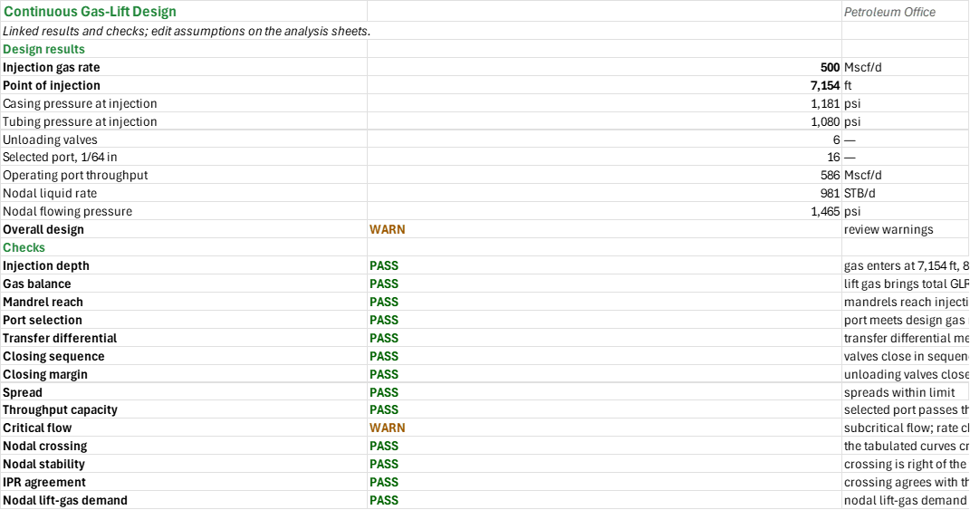
Example: For GL-1, the 1,000 STB/d liquid rate, 300 scf/STB formation GLR and 800 scf/STB target require 500 Mscf/d of lift gas. Injection is at 7,153.76 ft, with 1,180.98 psia in the casing and 1,080.50 psia in the tubing. At spacing factor 0.2, unloading selects a 16/64 in port and six unloading valves; the first is at 2,456.23 ft with 1,130.33 psia test-rack opening. The port passes 586.08 Mscf/d. With the linked GL-1 fluid and tubing conditions and a synthetic oil productivity index of 0.34 STB/d/psi chosen to align the nodal case with the design rate, the finite-grid nodal crossing is 980.56 STB/d at 1,464.74 psia and needs 490.28 Mscf/d of lift gas. The individual gas-lift and nodal calculations, run on the same unrounded inputs, give the same numbers.
Validity
Pressures are absolute. The injection pressure profile assumes all lift gas is present throughout the tubing; use a segmented traverse when gas enters above the node. Nodal assumes the packer depth is the node and uses total gas as free gas along the whole tubing at fixed liquid density and viscosity; compare against a measured survey and a segmented multiphase model. The nodal calculation holds total GLR constant as rate varies, so the lift gas it implies changes with rate; the nodal lift-gas check compares that demand with both the design gas rate and port capacity. The default crossing needs about 490 Mscf/d, within the 500 Mscf/d design and 586 Mscf/d port. A higher productivity may require more gas than either supplies and must be redesigned. No crossing on the displayed grid does not prove no crossing exists outside it. The design permits ten mandrels, assumes a straight transfer line and uses an illustrative port catalogue. The chart's tubing line is a straight approximation, not the calculated Hagedorn-Brown profile. The top mandrel depth balances full kickoff pressure, whereas its opening setting uses kickoff less the first drop; the first plotted kickoff balance therefore exceeds its opening setting by that drop. Review the pressure, spacing, transfer, closing and mechanical limits with the vendor.
The add-in has no dedicated valve-spacing or port-size functions; their screening equations are written in sheet cells with the valve functions. The throughput curve is omitted from this compact workbook; the valve throughput blueprint draws it. Compare correlations and validate the final design for the well.
References
- American Petroleum Institute. API RP 11V6, Recommended Practice for Design of Continuous Flow Gas Lift Installations Using Injection Pressure Operated Valves.
- Brown, K.E. (1980). The Technology of Artificial Lift Methods, Vol. 2a. PennWell (gas lift: injection point, unloading valve spacing and valve setting).
- Takacs, G. (2005). Gas Lift Manual. PennWell.
- Hagedorn, A.R. and Brown, K.E. (1965). Experimental Study of Pressure Gradients Occurring During Continuous Two-Phase Flow in Small-Diameter Vertical Conduits. JPT 17(4), 475-484.
- Vogel, J.V. (1968). Inflow Performance Relationships for Solution-Gas Drive Wells. JPT 20(1), 83-92.
- Beggs, H.D. and Brill, J.P. (1973). A Study of Two-Phase Flow in Inclined Pipes. JPT 25(5), 607-617.
Inputs
| Input | Unit | Default | Name |
|---|---|---|---|
| Surface operating injection pressure | psia | 1,000 | GDI_Ps |
| Lift-gas specific gravity | — | 0.65 | GDI_SG |
| Surface temperature | °F | 80 | GDI_Ts |
| Temperature at the packer depth | °F | 200 | GDI_Tb |
| Packer depth, the deepest injection point | ft | 8,000 | GDI_Dpk |
| Flowing wellhead pressure | psia | 120 | GDI_Pwh |
| Liquid rate | STB/d | 1,000 | GDI_Ql |
| Formation gas-liquid ratio | scf/STB | 300 | GDI_GLRf |
| Target total gas-liquid ratio | scf/STB | 800 | GDI_GLRt |
| Tubing inner diameter | in | 2.441 | GDI_ID |
| Tubing relative roughness | — | 0.0006 | GDI_Rough |
| Liquid specific gravity | — | 0.9 | GDI_SGl |
| Liquid viscosity | cP | 2 | GDI_Ul |
| Gas-liquid surface tension | dyne/cm | 30 | GDI_IFT |
| Minimum valve differential | psi | 100 | GDI_dPmin |
| Least injection depth, share of packer depth | % | 75 | GDI_PoiMin |
| Surface kickoff pressure | psia | 1,200 | GDU_Pko |
| Surface opening pressure drop per valve | psi | 25 | GDU_Drop |
| Kill-fluid gradient | psi/ft | 0.465 | GDU_Gs |
| Spacing factor | — | 0.2 | GDU_Fs |
| Minimum transfer differential | psi | 100 | GDU_dPmin |
| Discharge coefficient | — | 0.6 | GDU_Cd |
| Specific heat ratio | — | 1.28 | GDU_k |
| Bellows area | in² | 0.77 | GDU_Ab |
| Spring tension as pressure | psi | 0 | GDU_St |
| Maximum accepted spread | psi | 100 | GDU_SpreadMax |
| Average reservoir pressure | psia | 4,000 | GDN_Pr |
| Bubble-point pressure | psia | 2,620 | GDN_Pb |
| Oil productivity index above bubble point (synthetic, aligned to the design rate) | STB/d/psi | 0.34 | GDN_J |
| Water-oil ratio | — | 0.25 | GDN_WOR |
| Largest crossing miss against the IPR | % | 1 | GDN_IprTol |
Sheets
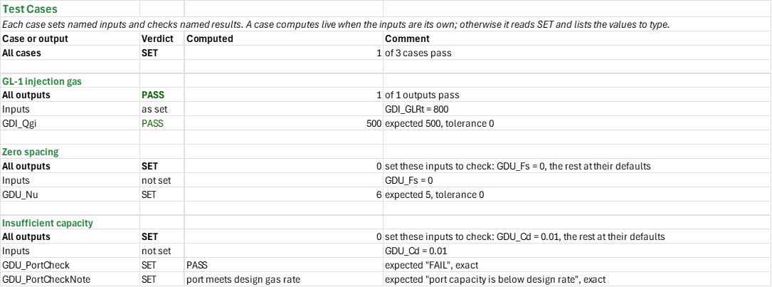
Guide— the workflow through the sheets and the scope and limitations of the screening.Injection— GL-1's lift gas, the gas properties and balance, the point of injection at the minimum valve differential, and the static gas and Hagedorn-Brown flowing pressure profiles.Unloading— the gas column and operating port, the IPO unloading valve schedule with dome, closing and test-rack pressures, and the pressure-depth design lines, charted.Throughput— Thornhill-Craver capacity and the critical-flow screen at the selected port, from the linked design conditions.Nodal— the composite IPR and the Beggs-Brill lifted tubing curve on Injection's conditions, their operating point and the lift gas it needs.Summary— the design results and every check under one verdict.Test Cases— the worked example and other cases, with expected and computed results.
One chart: the gas-lift design lines on Unloading (unloading, kickoff casing, operating casing, transfer and a linear tubing line).
Functions used
Names (197)
| Name | Refers to | Comment |
|---|---|---|
GDI_BalanceCheck |
Injection!$B$42 |
Gas balance check verdict |
GDI_BalanceCheckNote |
Injection!$C$42 |
Gas balance check comment |
GDI_DepthCheck |
Injection!$B$41 |
Injection depth check verdict |
GDI_DepthCheckNote |
Injection!$C$41 |
Injection depth check comment |
GDI_Dpk |
Injection!$B$8 |
Packer depth, the deepest injection point, ft |
GDI_GLRf |
Injection!$B$11 |
Formation gas-liquid ratio, scf/STB |
GDI_GLRi |
Injection!$B$27 |
Injection gas-liquid ratio, scf/STB |
GDI_GLRt |
Injection!$B$12 |
Target total gas-liquid ratio, scf/STB |
GDI_GLRtot |
Injection!$B$28 |
Total gas-liquid ratio with lift gas, scf/STB |
GDI_Gbot |
Injection!$B$33 |
Gas gradient over the column to the packer, psi/ft |
GDI_ID |
Injection!$B$13 |
Tubing inner diameter, in |
GDI_IFT |
Injection!$B$17 |
Gas-liquid surface tension, dyne/cm |
GDI_Inputs |
Injection!$B$4:$B$19 |
Injection pressure, gas, well, tubing, fluid and minimum differential inputs |
GDI_POI |
Injection!$B$35 |
Point of injection, ft |
GDI_Pbot |
Injection!$B$32 |
Injection gas pressure at packer depth, psi |
GDI_PcPOI |
Injection!$B$37 |
Casing pressure at the point of injection, psi |
GDI_PoiMin |
Injection!$B$19 |
Least injection depth, share of packer depth, % |
GDI_PoiShare |
Injection!$B$40 |
Point of injection, share of packer depth, % |
GDI_Ppc |
Injection!$B$25 |
Pseudo-critical pressure (Standing), psi |
GDI_PressureData |
Injection!$A$47:$I$55 |
Depth, temperature, two-pass casing gas column, flowing tubing pressure and margin |
GDI_Ps |
Injection!$B$4 |
Surface operating injection pressure, psi |
GDI_PtPOI |
Injection!$B$38 |
Tubing pressure at the point of injection, psi |
GDI_Pwh |
Injection!$B$9 |
Flowing wellhead pressure, psi |
GDI_Qgi |
Injection!$B$26 |
Injection gas rate for the target GLR, Mscf/d |
GDI_Qgt |
Injection!$B$29 |
Total gas rate in the tubing above the valve, Mscf/d |
GDI_Ql |
Injection!$B$10 |
Liquid rate, STB/d |
GDI_R0 |
Injection!$B$20 |
Rankine at 0 °F, °R |
GDI_Results |
Injection!$B$24:$B$42 |
Gas properties, gas balance, injection depth and pressures, and checks |
GDI_RhoW |
Injection!$B$21 |
Density of water, lb/ft³ |
GDI_Rough |
Injection!$B$14 |
Tubing relative roughness |
GDI_Rows |
Injection!$B$34 |
Profile rows holding the differential |
GDI_SG |
Injection!$B$5 |
Lift-gas specific gravity, air = 1 |
GDI_SGl |
Injection!$B$15 |
Liquid specific gravity, water = 1 |
GDI_TPOI |
Injection!$B$36 |
Temperature at the point of injection, °F |
GDI_Tb |
Injection!$B$7 |
Temperature at the packer depth, °F |
GDI_Tpc |
Injection!$B$24 |
Pseudo-critical temperature (Standing), °R |
GDI_Ts |
Injection!$B$6 |
Surface temperature, °F |
GDI_Ul |
Injection!$B$16 |
Liquid viscosity, cp |
GDI_dPmin |
Injection!$B$18 |
Minimum valve differential, psi |
GDI_dPv |
Injection!$B$39 |
Differential across the operating valve, psi |
GDN_AOF |
Nodal!$B$22 |
Oil AOF at zero flowing pressure, STB/d |
GDN_DD |
Nodal!$B$28 |
Drawdown, psi |
GDN_FlowCheck |
Nodal!$B$33 |
Flow check verdict |
GDN_FlowCheckNote |
Nodal!$C$33 |
Flow check comment |
GDN_GLR |
Nodal!$B$20 |
Total gas-liquid ratio, scf/bbl |
GDN_ID |
Nodal!$B$13 |
Tubing inner diameter, in |
GDN_IFT |
Nodal!$B$8 |
Gas-liquid surface tension, from Injection, dyne/cm |
GDN_Inputs |
Nodal!$B$4:$B$9 |
Independent reservoir and fluid inputs and the IPR check limit |
GDN_Ipr |
Nodal!$A$44:$C$60 |
Composite IPR from reservoir pressure to zero, four steps to the bubble point and twelve below it |
GDN_IprCheck |
Nodal!$B$35 |
IPR check verdict |
GDN_IprCheckNote |
Nodal!$C$35 |
IPR check comment |
GDN_IprErr |
Nodal!$B$30 |
Crossing rate relative to the IPR, % |
GDN_IprTol |
Nodal!$B$9 |
Largest crossing miss against the IPR, % |
GDN_J |
Nodal!$B$6 |
Oil productivity index above bubble point, STB/d/psi |
GDN_LiftCheck |
Nodal!$B$40 |
Nodal lift-gas consistency verdict |
GDN_LiftCheckNote |
Nodal!$C$40 |
Nodal lift-gas consistency comment |
GDN_PMin |
Nodal!$B$32 |
Pressure at the tubing curve minimum, psi |
GDN_Pb |
Nodal!$B$5 |
Bubble-point pressure, psi |
GDN_Pr |
Nodal!$B$4 |
Average reservoir pressure, psi |
GDN_Pwf |
Nodal!$B$25 |
Flowing pressure at the node, psi |
GDN_Pwh |
Nodal!$B$11 |
Wellhead pressure, psi |
GDN_QIpr |
Nodal!$B$29 |
IPR liquid rate at the node pressure, STB/d |
GDN_QL |
Nodal!$B$24 |
Liquid rate where the curves cross, STB/d |
GDN_QMin |
Nodal!$B$31 |
Rate at the tubing curve minimum, STB/d |
GDN_Qg |
Nodal!$B$27 |
Total gas rate, MMscf/d |
GDN_QgiRequired |
Nodal!$B$36 |
Lift gas needed at nodal crossing, Mscf/d |
GDN_Qo |
Nodal!$B$26 |
Oil rate, STB/d |
GDN_Results |
Nodal!$B$11:$B$36 |
Linked conditions, operating point, tubing minimum and checks |
GDN_RhoL |
Nodal!$B$19 |
Liquid density, lb/ft³ |
GDN_Rough |
Nodal!$B$14 |
Tubing relative roughness |
GDN_SGg |
Nodal!$B$17 |
Gas specific gravity, air = 1 |
GDN_Scf |
Nodal!$B$79 |
scf in an MMscf, scf/MMscf |
GDN_StabCheck |
Nodal!$B$34 |
Stability check verdict |
GDN_StabCheckNote |
Nodal!$C$34 |
Stability check comment |
GDN_TVD |
Nodal!$B$12 |
Packer depth, used as node TVD, ft |
GDN_Tbh |
Nodal!$B$16 |
Temperature at packer depth, °F |
GDN_Tm |
Nodal!$B$21 |
Mean tubing temperature, °F |
GDN_Twh |
Nodal!$B$15 |
Surface temperature, °F |
GDN_UL |
Nodal!$B$18 |
Liquid viscosity, cp |
GDN_Vert |
Nodal!$B$78 |
Vertical pipe angle from horizontal, ° |
GDN_Vlp |
Nodal!$A$64:$C$75 |
Liquid rates and total gas rates with Beggs-Brill node pressures |
GDN_WOR |
Nodal!$B$7 |
Water-oil ratio, bbl/STB |
GDS_Checks |
Summary!$B$15:$B$28 |
Checks linked to the analysis sheets |
GDS_Nu |
Summary!$B$8 |
Unloading valves |
GDS_Overall |
Summary!$B$13 |
Overall design verdict |
GDS_OverallNote |
Summary!$C$13 |
Overall design comment |
GDS_POI |
Summary!$B$5 |
Point of injection, ft |
GDS_PcPOI |
Summary!$B$6 |
Casing pressure at injection, psi |
GDS_Port |
Summary!$B$9 |
Selected port, 1/64 in |
GDS_PortCheck |
Summary!$B$18 |
Selected port capacity verdict |
GDS_PortCheckNote |
Summary!$C$18 |
Selected port capacity comment |
GDS_PtPOI |
Summary!$B$7 |
Tubing pressure at injection, psi |
GDS_Pwf |
Summary!$B$12 |
Nodal flowing pressure, psi |
GDS_QL |
Summary!$B$11 |
Nodal liquid rate, STB/d |
GDS_Qg |
Summary!$B$10 |
Operating port throughput, Mscf/d |
GDS_Qgi |
Summary!$B$4 |
Injection gas rate, Mscf/d |
GDS_Results |
Summary!$B$4:$B$13 |
Injection, unloading, port, nodal results and overall verdict |
GDT_Ab |
Throughput!$B$6 |
Bellows area, in² |
GDT_Ap |
Throughput!$B$15 |
Port area, in² |
GDT_CapacityCheck |
Throughput!$B$25 |
Port capacity verdict |
GDT_CapacityCheckNote |
Throughput!$C$25 |
Port capacity comment |
GDT_Cd |
Throughput!$B$4 |
Discharge coefficient |
GDT_Conditions |
Throughput!$B$4:$B$12 |
Linked valve geometry, pressures, gas properties and design rate |
GDT_CriticalCheck |
Throughput!$B$26 |
Critical flow verdict |
GDT_CriticalCheckNote |
Throughput!$C$26 |
Critical flow comment |
GDT_Loss10 |
Throughput!$B$24 |
Rate lost for 10 psi more tubing pressure, Mscf/d |
GDT_P1 |
Throughput!$B$7 |
Upstream casing pressure, psi |
GDT_P2 |
Throughput!$B$8 |
Downstream tubing pressure, psi |
GDT_P2c |
Throughput!$B$21 |
Tubing pressure below which the port chokes, psi |
GDT_PPEF |
Throughput!$B$17 |
Production pressure effect factor |
GDT_Qg |
Throughput!$B$18 |
Operating throughput, Mscf/d |
GDT_Qgi |
Throughput!$B$12 |
Design gas injection rate, Mscf/d |
GDT_Qmax |
Throughput!$B$22 |
Choked throughput, Mscf/d |
GDT_R |
Throughput!$B$16 |
Port to bellows area ratio |
GDT_Ratio |
Throughput!$B$19 |
Tubing to casing pressure ratio |
GDT_Rc |
Throughput!$B$20 |
Critical pressure ratio |
GDT_Results |
Throughput!$B$15:$B$26 |
Throughput, critical flow and checks |
GDT_SG |
Throughput!$B$9 |
Lift-gas specific gravity, air = 1 |
GDT_Share |
Throughput!$B$23 |
Operating share of choked rate, % |
GDT_T |
Throughput!$B$10 |
Temperature at the valve, °F |
GDT_dPort |
Throughput!$B$5 |
Selected port diameter, in |
GDT_k |
Throughput!$B$11 |
Specific heat ratio |
GDU_Ab |
Unloading!$B$11 |
Bellows area, in² |
GDU_Ap |
Unloading!$B$26 |
Port area, in² |
GDU_ApReq |
Unloading!$B$23 |
Required port area, in² |
GDU_Cd |
Unloading!$B$9 |
Discharge coefficient |
GDU_ClosingCheck |
Unloading!$B$37 |
Closing margin verdict |
GDU_ClosingCheckNote |
Unloading!$C$37 |
Closing margin comment |
GDU_Curve |
Unloading!$A$63:$H$83 |
Gas-lift unloading design |
GDU_D1 |
Unloading!$B$31 |
Top valve depth, ft |
GDU_Drop |
Unloading!$B$5 |
Surface opening pressure drop per valve, psi |
GDU_Dv1 |
Unloading!$C$50 |
Depth of valve 1, ft |
GDU_Dv10 |
Unloading!$C$59 |
Depth of valve 10, ft |
GDU_Dv2 |
Unloading!$C$51 |
Depth of valve 2, ft |
GDU_Dv3 |
Unloading!$C$52 |
Depth of valve 3, ft |
GDU_Dv4 |
Unloading!$C$53 |
Depth of valve 4, ft |
GDU_Dv5 |
Unloading!$C$54 |
Depth of valve 5, ft |
GDU_Dv6 |
Unloading!$C$55 |
Depth of valve 6, ft |
GDU_Dv7 |
Unloading!$C$56 |
Depth of valve 7, ft |
GDU_Dv8 |
Unloading!$C$57 |
Depth of valve 8, ft |
GDU_Dv9 |
Unloading!$C$58 |
Depth of valve 9, ft |
GDU_Fs |
Unloading!$B$7 |
Spacing factor, % |
GDU_G1 |
Unloading!$B$20 |
Gas gradient, first pass, psi/ft |
GDU_Gg |
Unloading!$B$21 |
Gas gradient, second pass, psi/ft |
GDU_Gs |
Unloading!$B$6 |
Kill-fluid gradient, psi/ft |
GDU_Inputs |
Unloading!$B$4:$B$13 |
Kickoff, spacing, valve and transfer inputs |
GDU_Nu |
Unloading!$B$30 |
Unloading valve count |
GDU_P1op |
Unloading!$B$22 |
Operating casing pressure at valve, psi |
GDU_Pko |
Unloading!$B$4 |
Surface kickoff pressure, psi |
GDU_Port |
Unloading!$B$25 |
Selected port (1/64 in) |
GDU_PortCheck |
Unloading!$B$34 |
Port capacity verdict |
GDU_PortCheckNote |
Unloading!$C$34 |
Port capacity comment |
GDU_Ports |
Unloading!$A$40:$E$46 |
Operating port candidates and capacity |
GDU_Ppc |
Unloading!$B$17 |
Pseudo-critical pressure, psi |
GDU_Ptr0 |
Unloading!$B$29 |
Transfer pressure at surface, psi |
GDU_Ptr1 |
Unloading!$G$50 |
Transfer pressure at valve 1, psia |
GDU_Ptr10 |
Unloading!$G$59 |
Transfer pressure at valve 10, psia |
GDU_Ptr2 |
Unloading!$G$51 |
Transfer pressure at valve 2, psia |
GDU_Ptr3 |
Unloading!$G$52 |
Transfer pressure at valve 3, psia |
GDU_Ptr4 |
Unloading!$G$53 |
Transfer pressure at valve 4, psia |
GDU_Ptr5 |
Unloading!$G$54 |
Transfer pressure at valve 5, psia |
GDU_Ptr6 |
Unloading!$G$55 |
Transfer pressure at valve 6, psia |
GDU_Ptr7 |
Unloading!$G$56 |
Transfer pressure at valve 7, psia |
GDU_Ptr8 |
Unloading!$G$57 |
Transfer pressure at valve 8, psia |
GDU_Ptr9 |
Unloading!$G$58 |
Transfer pressure at valve 9, psia |
GDU_Ptro1 |
Unloading!$B$32 |
Top valve test-rack opening, psi |
GDU_Qport |
Unloading!$B$28 |
Selected port capacity, Mscf/d |
GDU_R0 |
Unloading!$B$14 |
Rankine at zero Fahrenheit, °R |
GDU_ReachCheck |
Unloading!$B$33 |
Mandrel reach verdict |
GDU_ReachCheckNote |
Unloading!$C$33 |
Mandrel reach comment |
GDU_Results |
Unloading!$B$16:$B$38 |
Gas column, port, valve schedule and checks |
GDU_Rport |
Unloading!$B$27 |
Port to bellows ratio |
GDU_SequenceCheck |
Unloading!$B$36 |
Closing sequence verdict |
GDU_SequenceCheckNote |
Unloading!$C$36 |
Closing sequence comment |
GDU_Small |
Unloading!$B$24 |
Ports too small |
GDU_SpreadCheck |
Unloading!$B$38 |
Valve spread verdict |
GDU_SpreadCheckNote |
Unloading!$C$38 |
Valve spread comment |
GDU_SpreadMax |
Unloading!$B$13 |
Maximum accepted spread, psi |
GDU_St |
Unloading!$B$12 |
Spring tension as pressure, psi |
GDU_TPOI |
Unloading!$B$18 |
Temperature at injection, °F |
GDU_Tcol |
Unloading!$B$19 |
Average gas-column temperature, °F |
GDU_Tpc |
Unloading!$B$16 |
Pseudo-critical temperature, °R |
GDU_TransferCheck |
Unloading!$B$35 |
Transfer differential verdict |
GDU_TransferCheckNote |
Unloading!$C$35 |
Transfer differential comment |
GDU_Tro1 |
Unloading!$L$50 |
Test-rack opening of valve 1, psia |
GDU_Tro10 |
Unloading!$L$59 |
Test-rack opening of valve 10, psia |
GDU_Tro2 |
Unloading!$L$51 |
Test-rack opening of valve 2, psia |
GDU_Tro3 |
Unloading!$L$52 |
Test-rack opening of valve 3, psia |
GDU_Tro4 |
Unloading!$L$53 |
Test-rack opening of valve 4, psia |
GDU_Tro5 |
Unloading!$L$54 |
Test-rack opening of valve 5, psia |
GDU_Tro6 |
Unloading!$L$55 |
Test-rack opening of valve 6, psia |
GDU_Tro7 |
Unloading!$L$56 |
Test-rack opening of valve 7, psia |
GDU_Tro8 |
Unloading!$L$57 |
Test-rack opening of valve 8, psia |
GDU_Tro9 |
Unloading!$L$58 |
Test-rack opening of valve 9, psia |
GDU_Valves |
Unloading!$A$50:$O$59 |
Unloading valve spacing and settings |
GDU_dPmin |
Unloading!$B$8 |
Minimum transfer differential, psi |
GDU_k |
Unloading!$B$10 |
Specific heat ratio |
Details
| Opens in | Needs the Petroleum Office add-in: its PO functions show #NAME? without it once Excel recalculates. |
| File | GasLiftDesign.xlsx, 45 KB |
| Category | Production |
| For agents and tools | Descriptor (.md) |