ESP System Design
Description
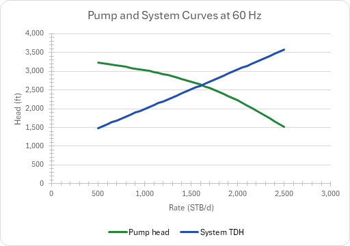
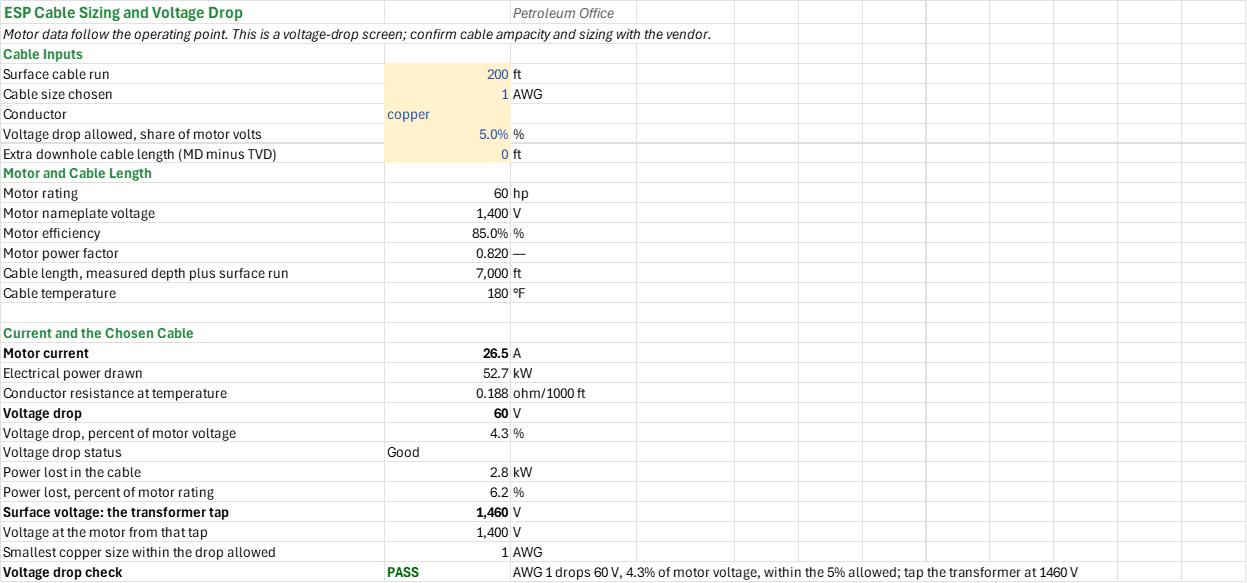
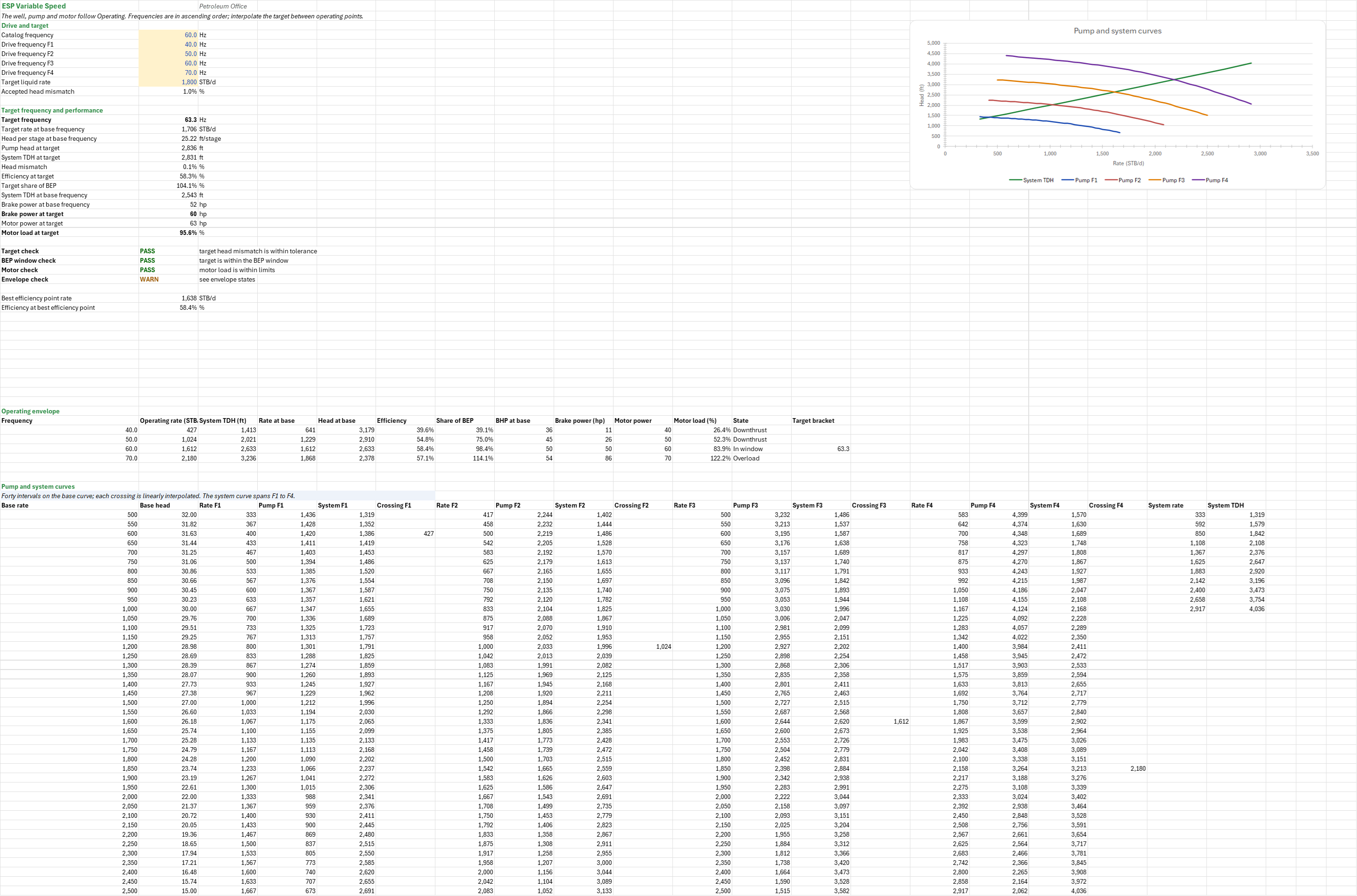
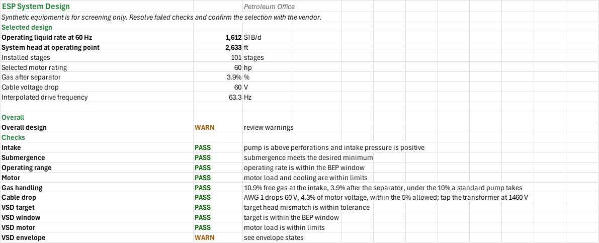
Which pump stages and motor does one well's electric submersible pump need, and will the installation run? You enter the well's depths, reservoir pressure, productivity index and design rate, the fluid, the cable and the drive frequencies. You read off the stages and motor, the operating point where the pump head crosses the system curve, the free gas at the intake and the separator it calls for, the cable voltage drop, and the drive frequency that delivers a target rate.
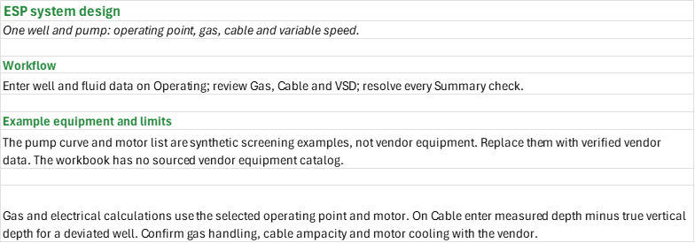
How to use it: Enter the well, fluid, motor limits and design rate on the Operating sheet, and replace its synthetic single-stage pump curve and motor list with verified vendor data, in increasing rate and rating order. Enter the oil share, GOR, gravities and separator on the Gas sheet, the surface run, cable size, conductor, allowed voltage drop and deviation allowance on the Cable sheet, and the drive frequencies and target rate on the VSD sheet. Resolve every check on the Summary, and confirm gas handling, cable ampacity and motor cooling with the vendor.
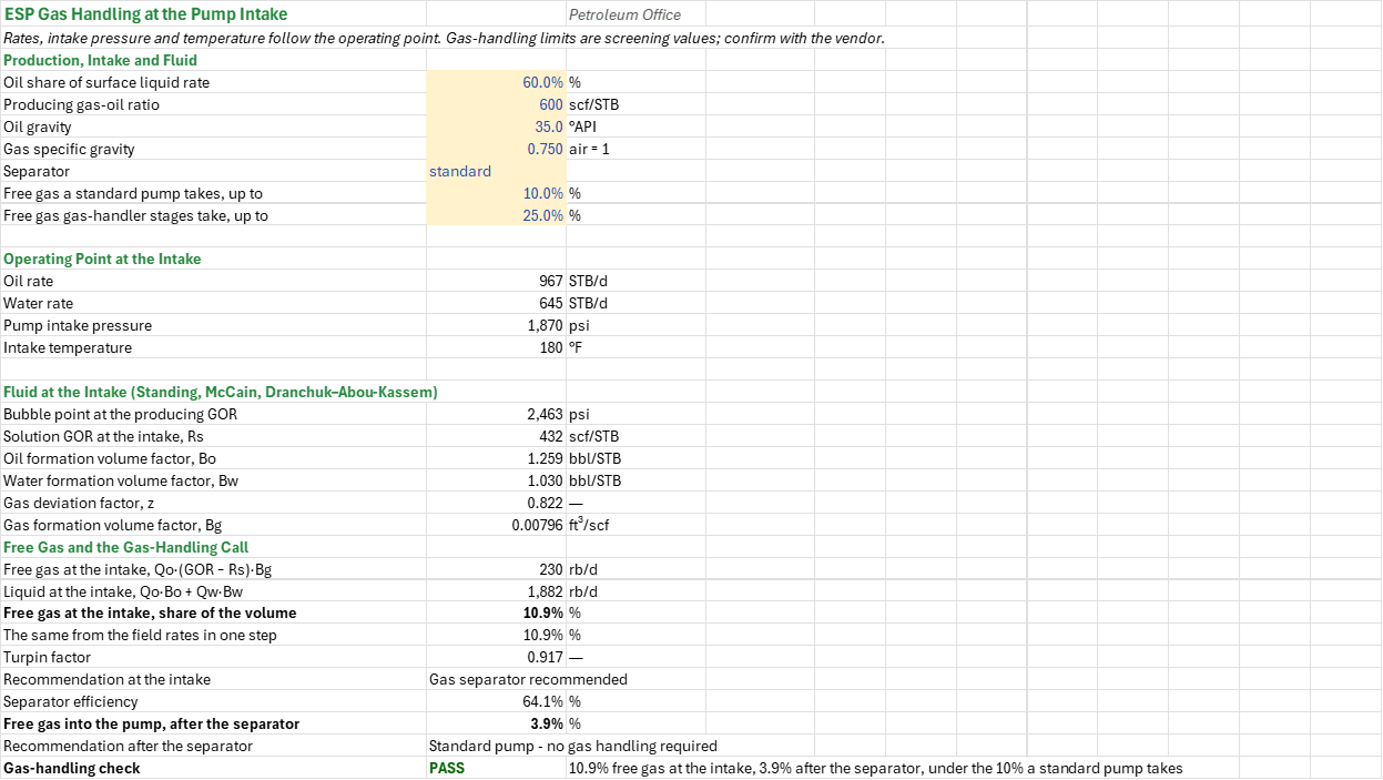
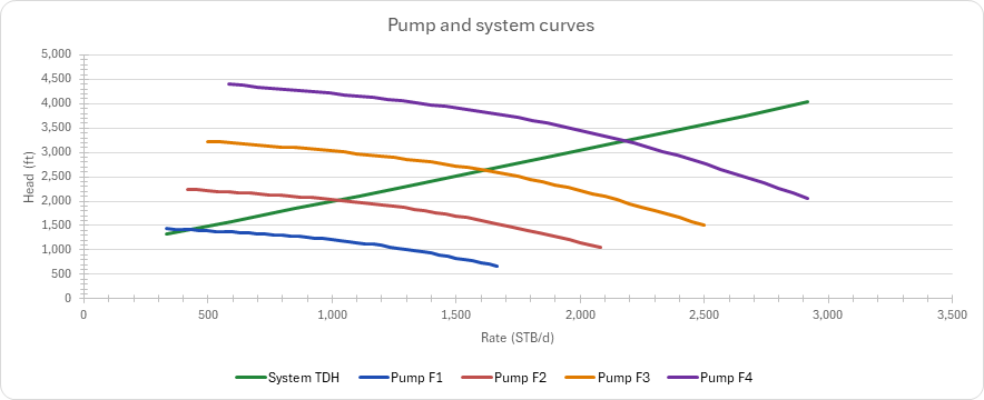
Method: The operating sheet uses the linear productivity index and the pump intake pressure to calculate the system head, and interpolates the unique crossing of the pump and system curves on a 41-point grid. The gas sheet takes the fluid at the intake from Standing's, McCain's and Dranchuk–Abou-Kassem's correlations, finds the free-gas void fraction before and after the separator, and screens it against what a standard pump (up to 10 % free gas) and gas-handler stages (up to 25 %) take, with Turpin's factor alongside. The cable sheet estimates the resistive three-phase voltage drop and power loss of the chosen cable and the smallest size that keeps the drop within the allowance. The variable-speed sheet moves the same pump curve by the affinity laws (rate with frequency, head with its square, power with its cube) and interpolates the target frequency between operating points.
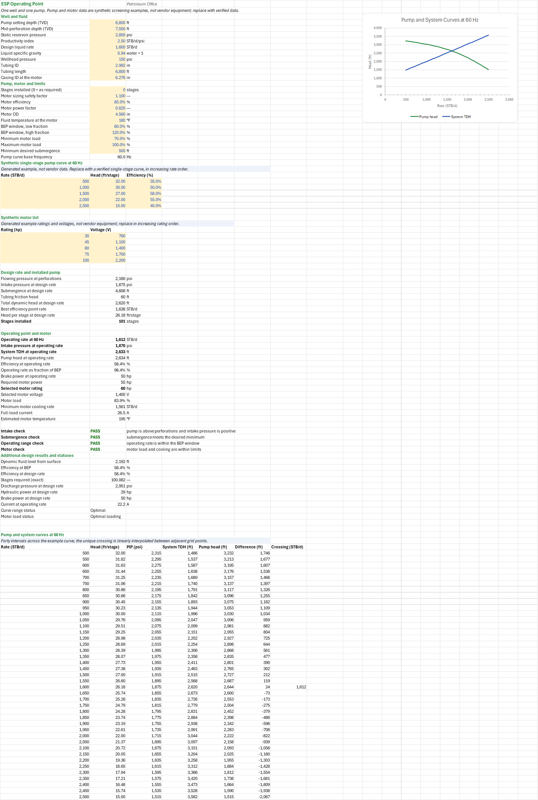
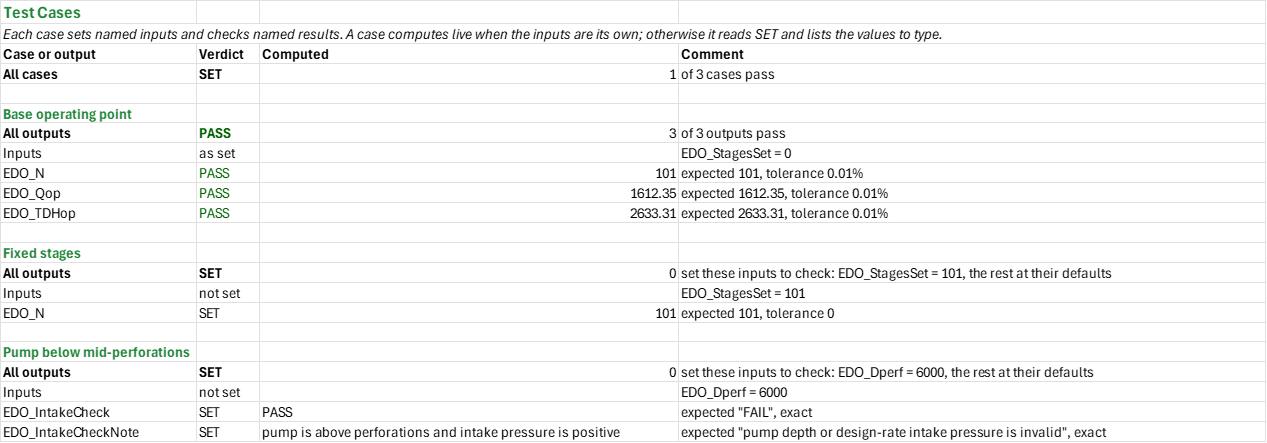
Example: The operating-point blueprint's default well has pump depth 6,800 ft, mid-perforations 7,500 ft, reservoir pressure 2,800 psi, productivity index 2.5 STB/d/psi and a 1,600 STB/d design rate. On its synthetic 60 Hz pump curve it needs 101 stages and produces 1,612.35 STB/d at 2,633.31 ft of system head, the same numbers the ESP operating-point blueprint gives on the same inputs. The pump curve and motor data are not vendor specifications.
Validity
The pump and motor data are generated screening examples, not sourced vendor equipment; replace them with verified equipment data before design. A sourced vendor-equipment catalog is not yet included. Use measured well test and PVT data and consult the vendor on pump gas tolerance, motor cooling, starting voltage and cable ampacity. The gas model assumes no slip and uses screening separator efficiencies; the cable drop is resistive only and its minimum-size calculation is for copper. The zero deviation allowance assumes the pump's measured depth equals its true vertical depth; enter measured depth minus true vertical depth for a deviated well. The gas pressure-sensitivity and cable-size comparison charts are left out here; use the individual blueprints for those details. The drive frequency is interpolated, not optimised; the add-in has no optimum-frequency function.
References
- Takacs, G. (2009). Electrical Submersible Pumps Manual: Design, Operations, and Maintenance. Gulf Professional Publishing.
- American Petroleum Institute. API RP 11S4, Recommended Practice for Sizing and Selection of Electric Submersible Pump Installations.
- Standing, M.B. (1947). A Pressure-Volume-Temperature Correlation for Mixtures of California Oils and Gases. Drilling and Production Practice, API, 275-287.
- McCain, W.D. Jr. (1990). The Properties of Petroleum Fluids, 2nd ed. PennWell.
- Dranchuk, P.M. and Abou-Kassem, J.H. (1975). Calculation of Z Factors for Natural Gases Using Equations of State. J. Can. Pet. Tech. 14(3), 34-36.
- Turpin, J.L., Lea, J.F. and Bearden, J.L. (1986). Gas-Liquid Flow Through Centrifugal Pumps: Correlation of Data. Proceedings of the Third International Pump Symposium, Texas A&M University.
Inputs
| Input | Unit | Default | Name |
|---|---|---|---|
| Pump setting depth (TVD) | ft | 6800 | EDO_Dpump |
| Mid-perforation depth (TVD) | ft | 7500 | EDO_Dperf |
| Static reservoir pressure | psi | 2800 | EDO_Pr |
| Productivity index | STB/d/psi | 2.5 | EDO_PI |
| Design liquid rate | STB/d | 1600 | EDO_Q |
| Liquid specific gravity | — | 0.94 | EDO_SG |
| Wellhead pressure | psi | 150 | EDO_WHP |
| Tubing ID | in. | 2.992 | EDO_TubID |
| Tubing length | ft | 6800 | EDO_TubL |
| Casing ID at the motor | in. | 6.276 | EDO_CasingID |
| Stages installed (0 = as required) | stages | 0 | EDO_StagesSet |
| Motor sizing safety factor | — | 1.1 | EDO_SF |
| Motor efficiency | % | 85 % | EDO_MotorEff |
| Motor power factor | — | 0.82 | EDO_PF |
| Motor OD | in. | 4.56 | EDO_MotorOD |
| Fluid temperature at the motor | °F | 180 | EDO_T |
| BEP window, low and high fraction | % | 80 %, 120 % | EDO_BepLo, EDO_BepHi |
| Minimum and maximum motor load | % | 70 %, 100 % | EDO_LoadMin, EDO_LoadMax |
| Minimum desired submergence | ft | 500 | EDO_MinSubm |
| Synthetic single-stage pump curve at 60 Hz: rate, head, efficiency | STB/d, ft/stage, % | generated example | EDO_CurveQ, EDO_CurveH, EDO_CurveE |
| Synthetic motor list: rating, voltage | hp, V | generated example | EDO_MotorHPs, EDO_MotorVs |
| Oil share of surface liquid rate | % | 60 % | EDG_OilShare |
| Producing gas-oil ratio | scf/STB | 600 | EDG_GOR |
| Oil gravity | °API | 35 | EDG_API |
| Gas specific gravity | — | 0.75 | EDG_SGg |
| Separator (standard, advanced or tandem) | — | standard | EDG_SepType |
| Free gas a standard pump takes, up to | % | 10 % | EDG_VoidStd |
| Free gas gas-handler stages take, up to | % | 25 % | EDG_VoidAgh |
| Surface cable run | ft | 200 | EDC_SurfaceRun |
| Cable size chosen | AWG | 1 | EDC_AWG |
| Conductor (copper or aluminum) | — | copper | EDC_Material |
| Voltage drop allowed, share of motor volts | % | 5 % | EDC_MaxDrop |
| Extra downhole cable length (MD minus TVD) | ft | 0 | EDC_DeviationExtra |
| Catalog frequency | Hz | 60 | EDV_Fb |
| Drive frequencies F1 to F4 | Hz | 40, 50, 60, 70 | EDV_F1, EDV_F2, EDV_F3, EDV_F4 |
| Target liquid rate | STB/d | 1800 | EDV_Qt |
Sheets
Guide— the workflow through the sheets, and why the example equipment is synthetic and must be replaced with vendor data.Operating— the well and fluid, the pump, motor and limits, the synthetic 60 Hz pump curve and motor list, the stages and motor chosen, the operating point and motor load, and the pump and system curves charted at 60 Hz.Gas— the operating point at the intake, the fluid there, the free gas before and after the separator, and the gas-handling call.Cable— the motor and cable length, the current, the chosen cable's voltage drop and power loss, and the smallest cable that meets the allowance.VSD— the drive frequencies and target rate, the target frequency and its performance, the operating envelope, and the pump curves at each frequency against the system curve.Summary— the selected design and every check under one verdict.Test Cases— the worked example and other cases, with expected and computed results.
Functions used
Names (195)
| Name | Refers to | Comment |
|---|---|---|
PO.ESP.Affinity.HeadLAMBDA |
=LAMBDA(h, f, f_base, h*(f/f_base)^2) |
Affinity law: head at frequency f from the head at f_base, in the units of h. |
PO.ESP.Affinity.PowerLAMBDA |
=LAMBDA(p, f, f_base, p*(f/f_base)^3) |
Affinity law: power at frequency f from the power at f_base, in the units of p. |
PO.ESP.Affinity.RateLAMBDA |
=LAMBDA(q, f, f_base, q*f/f_base) |
Affinity law: rate at frequency f from the rate at f_base, in the units of q. |
EDC_AWG |
Cable!$B$5 |
Cable size chosen, AWG |
EDC_Check |
Cable!$B$29 |
Voltage drop check verdict |
EDC_CheckNote |
Cable!$C$29 |
Voltage drop check comment |
EDC_DeviationExtra |
Cable!$B$8 |
Extra downhole cable length (MD minus TVD), ft |
EDC_HP |
Cable!$B$10 |
Motor rating, hp |
EDC_I |
Cable!$B$18 |
Motor current, A |
EDC_Inputs |
Cable!$B$4:$B$8 |
Surface run, cable size, conductor, voltage drop allowed and deviation allowance |
EDC_L |
Cable!$B$14 |
Cable length, measured depth plus surface run, ft |
EDC_Material |
Cable!$B$6 |
Conductor |
EDC_MaxDrop |
Cable!$B$7 |
Voltage drop allowed, share of motor volts, % |
EDC_MinAWG |
Cable!$B$28 |
Smallest copper size within the drop allowed, AWG |
EDC_MotorEff |
Cable!$B$12 |
Motor efficiency, % |
EDC_Operating |
Cable!$B$10:$B$15 |
Selected motor, cable length and temperature |
EDC_PF |
Cable!$B$13 |
Motor power factor |
EDC_Ploss |
Cable!$B$24 |
Power lost in the cable, kW |
EDC_PlossPct |
Cable!$B$25 |
Power lost, percent of motor rating, % |
EDC_R |
Cable!$B$20 |
Conductor resistance at temperature, ohm/1000 ft |
EDC_Results |
Cable!$B$18:$B$29 |
Current, resistance, drop and loss, transformer tap, copper minimum size and check |
EDC_Status |
Cable!$B$23 |
Voltage drop status |
EDC_SurfaceRun |
Cable!$B$4 |
Surface cable run, ft |
EDC_T |
Cable!$B$15 |
Cable temperature, °F |
EDC_V |
Cable!$B$11 |
Motor nameplate voltage, V |
EDC_Vdrop |
Cable!$B$21 |
Voltage drop, V |
EDC_VdropPct |
Cable!$B$22 |
Voltage drop, percent of motor voltage, % |
EDC_Vmotor |
Cable!$B$27 |
Voltage at the motor from that tap, V |
EDC_Vsurf |
Cable!$B$26 |
Surface voltage: the transformer tap, V |
EDC_kW |
Cable!$B$19 |
Electrical power drawn, kW |
EDG_API |
Gas!$B$6 |
Oil gravity, °API |
EDG_Advice |
Gas!$B$31 |
Recommendation at the intake |
EDG_AdviceSep |
Gas!$B$34 |
Recommendation after the separator |
EDG_Bg |
Gas!$B$24 |
Gas formation volume factor, Bg, ft³/scf |
EDG_Bo |
Gas!$B$21 |
Oil formation volume factor, Bo, bbl/STB |
EDG_Bw |
Gas!$B$22 |
Water formation volume factor, Bw, bbl/STB |
EDG_Check |
Gas!$B$35 |
Gas-handling check verdict |
EDG_CheckNote |
Gas!$C$35 |
Gas-handling check comment |
EDG_GOR |
Gas!$B$5 |
Producing gas-oil ratio, scf/STB |
EDG_Inputs |
Gas!$B$4:$B$10 |
Oil share, fluid properties, separator and gas-handling screening limits |
EDG_OilShare |
Gas!$B$4 |
Oil share of surface liquid rate, % |
EDG_Operating |
Gas!$B$13:$B$16 |
Operating-point rates, intake pressure and temperature |
EDG_PIP |
Gas!$B$15 |
Pump intake pressure, psi |
EDG_Pb |
Gas!$B$19 |
Bubble point at the producing GOR, psi |
EDG_Qg |
Gas!$B$26 |
Free gas at the intake, Qo·(GOR − Rs)·Bg, rb/d |
EDG_Ql |
Gas!$B$27 |
Liquid at the intake, Qo·Bo + Qw·Bw, rb/d |
EDG_Qo |
Gas!$B$13 |
Oil rate, STB/d |
EDG_Qw |
Gas!$B$14 |
Water rate, STB/d |
EDG_Results |
Gas!$B$19:$B$35 |
Intake PVT, free gas and liquid, separator performance and gas-handling check |
EDG_Rs |
Gas!$B$20 |
Solution GOR at the intake, Rs, scf/STB |
EDG_SGg |
Gas!$B$7 |
Gas specific gravity, air = 1 |
EDG_SepEff |
Gas!$B$32 |
Separator efficiency, % |
EDG_SepType |
Gas!$B$8 |
Separator |
EDG_T |
Gas!$B$16 |
Intake temperature, °F |
EDG_Turpin |
Gas!$B$30 |
Turpin factor |
EDG_Void |
Gas!$B$28 |
Free gas at the intake, share of the volume, % |
EDG_VoidAgh |
Gas!$B$10 |
Free gas gas-handler stages take, up to, % |
EDG_VoidFull |
Gas!$B$29 |
The same from the field rates in one step, % |
EDG_VoidSep |
Gas!$B$33 |
Free gas into the pump, after the separator, % |
EDG_VoidStd |
Gas!$B$9 |
Free gas a standard pump takes, up to, % |
EDG_z |
Gas!$B$23 |
Gas deviation factor, z |
EDO_AdditionalResults |
Operating!$B$76:$B$85 |
Additional design results and operating statuses |
EDO_Amps |
Operating!$B$68 |
Full-load current, A |
EDO_AmpsOp |
Operating!$B$83 |
Current at operating rate, A |
EDO_BHP |
Operating!$B$82 |
Brake power at design rate, hp |
EDO_BHPop |
Operating!$B$62 |
Brake power at operating rate, hp |
EDO_BepFrac |
Operating!$B$61 |
Operating rate as fraction of BEP, % |
EDO_BepHi |
Operating!$B$22 |
BEP window, high fraction, % |
EDO_BepLo |
Operating!$B$21 |
BEP window, low fraction, % |
EDO_CasingID |
Operating!$B$13 |
Casing ID at the motor, in |
EDO_CurveE |
Operating!$C$30:$C$34 |
Single-stage efficiencies, fraction |
EDO_CurveH |
Operating!$B$30:$B$34 |
Single-stage heads, ft/stage |
EDO_CurveQ |
Operating!$A$30:$A$34 |
Single-stage rates, STB/d |
EDO_Dperf |
Operating!$B$5 |
Mid-perforation depth (TVD), ft |
EDO_Dpump |
Operating!$B$4 |
Pump setting depth (TVD), ft |
EDO_Eff |
Operating!$B$78 |
Efficiency at design rate, % |
EDO_EffBEP |
Operating!$B$77 |
Efficiency at BEP, % |
EDO_EffOp |
Operating!$B$60 |
Efficiency at operating rate, % |
EDO_Fbase |
Operating!$B$26 |
Pump curve base frequency, Hz |
EDO_FluidLevel |
Operating!$B$76 |
Dynamic fluid level from surface, ft |
EDO_Grid |
Operating!$A$91:$G$131 |
Pump and system heads and interpolated crossing at 60 Hz |
EDO_HHP |
Operating!$B$81 |
Hydraulic power at design rate, hp |
EDO_Hfric |
Operating!$B$49 |
Tubing friction head, ft |
EDO_Hop |
Operating!$B$59 |
Pump head at operating rate, ft |
EDO_Hstg |
Operating!$B$52 |
Head per stage at design rate, ft/stage |
EDO_Inputs |
Operating!$B$4:$B$25 |
Well, fluid, motor and design limits |
EDO_IntakeCheck |
Operating!$B$71 |
Intake check verdict |
EDO_IntakeCheckNote |
Operating!$C$71 |
Intake check comment |
EDO_Load |
Operating!$B$66 |
Motor load, % |
EDO_LoadMax |
Operating!$B$24 |
Maximum motor load, % |
EDO_LoadMin |
Operating!$B$23 |
Minimum motor load, % |
EDO_LoadStatus |
Operating!$B$85 |
Motor load status |
EDO_MinSubm |
Operating!$B$25 |
Minimum desired submergence, ft |
EDO_Motor |
Operating!$B$64 |
Selected motor rating, hp |
EDO_MotorCheck |
Operating!$B$74 |
Motor check verdict |
EDO_MotorCheckNote |
Operating!$C$74 |
Motor check comment |
EDO_MotorEff |
Operating!$B$17 |
Motor efficiency, % |
EDO_MotorHPs |
Operating!$A$39:$A$43 |
Motor ratings, hp |
EDO_MotorOD |
Operating!$B$19 |
Motor OD, in |
EDO_MotorReq |
Operating!$B$63 |
Required motor power, hp |
EDO_MotorT |
Operating!$B$69 |
Estimated motor temperature, °F |
EDO_MotorV |
Operating!$B$65 |
Selected motor voltage, V |
EDO_MotorVs |
Operating!$B$39:$B$43 |
Motor voltages, V |
EDO_N |
Operating!$B$53 |
Stages installed, stages |
EDO_PF |
Operating!$B$18 |
Motor power factor |
EDO_PI |
Operating!$B$7 |
Productivity index, STB/d/psi |
EDO_PIP |
Operating!$B$47 |
Intake pressure at design rate, psi |
EDO_PIPop |
Operating!$B$57 |
Intake pressure at operating rate, psi |
EDO_Pdis |
Operating!$B$80 |
Discharge pressure at design rate, psi |
EDO_Pr |
Operating!$B$6 |
Static reservoir pressure, psi |
EDO_Pwf |
Operating!$B$46 |
Flowing pressure at perforations, psi |
EDO_Q |
Operating!$B$8 |
Design liquid rate, STB/d |
EDO_QBEP |
Operating!$B$51 |
Best efficiency point rate, STB/d |
EDO_Qcool |
Operating!$B$67 |
Minimum motor cooling rate, STB/d |
EDO_Qop |
Operating!$B$56 |
Operating rate at 60 Hz, STB/d |
EDO_RangeCheck |
Operating!$B$73 |
Operating range check verdict |
EDO_RangeCheckNote |
Operating!$C$73 |
Operating range check comment |
EDO_RangeStatus |
Operating!$B$84 |
Curve range status |
EDO_Results |
Operating!$B$46:$B$74 |
Design and operating point, motor selection and checks |
EDO_SF |
Operating!$B$16 |
Motor sizing safety factor |
EDO_SG |
Operating!$B$9 |
Liquid specific gravity, water = 1 |
EDO_StagesExact |
Operating!$B$79 |
Stages required (exact) |
EDO_StagesSet |
Operating!$B$15 |
Stages installed (0 = as required), stages |
EDO_Subm |
Operating!$B$48 |
Submergence at design rate, ft |
EDO_SubmCheck |
Operating!$B$72 |
Submergence check verdict |
EDO_SubmCheckNote |
Operating!$C$72 |
Submergence check comment |
EDO_SystemCurve |
Operating!$A$91:$E$131 |
Pump and System Curves at 60 Hz |
EDO_T |
Operating!$B$20 |
Fluid temperature at the motor, °F |
EDO_TDH |
Operating!$B$50 |
Total dynamic head at design rate, ft |
EDO_TDHop |
Operating!$B$58 |
System TDH at operating rate, ft |
EDO_TubID |
Operating!$B$11 |
Tubing ID, in |
EDO_TubL |
Operating!$B$12 |
Tubing length, ft |
EDO_WHP |
Operating!$B$10 |
Wellhead pressure, psi |
EDV_BHP1 |
VSD!$I$46 |
Brake power at F1 |
EDV_BHP2 |
VSD!$I$47 |
Brake power at F2 |
EDV_BHP3 |
VSD!$I$48 |
Brake power at F3 |
EDV_BHP4 |
VSD!$I$49 |
Brake power at F4 |
EDV_BHPbt |
VSD!$B$22 |
Brake power at base frequency, hp |
EDV_BHPt |
VSD!$B$23 |
Brake power at target, hp |
EDV_EffBEP |
VSD!$B$33 |
Efficiency at best efficiency point, % |
EDV_EffT |
VSD!$B$19 |
Efficiency at target, % |
EDV_Envelope |
VSD!$A$46:$M$49 |
Operating points, motor loads and target brackets at four frequencies |
EDV_EnvelopeCheck |
VSD!$B$30 |
Envelope check verdict |
EDV_EnvelopeCheckNote |
VSD!$C$30 |
Envelope check comment |
EDV_F1 |
VSD!$B$5 |
Drive frequency F1, Hz |
EDV_F2 |
VSD!$B$6 |
Drive frequency F2, Hz |
EDV_F3 |
VSD!$B$7 |
Drive frequency F3, Hz |
EDV_F4 |
VSD!$B$8 |
Drive frequency F4, Hz |
EDV_Fb |
VSD!$B$4 |
Catalog frequency, Hz |
EDV_Ft |
VSD!$B$13 |
Target frequency, Hz |
EDV_Grid |
VSD!$A$55:$T$95 |
Base grid and each frequency's pump, system and crossing, with the system curve |
EDV_Hbt |
VSD!$B$15 |
Head per stage at base frequency, ft/stage |
EDV_Ht |
VSD!$B$16 |
Pump head at target, ft |
EDV_Inputs |
VSD!$B$4:$B$9 |
Drive frequencies and target rate |
EDV_Load1 |
VSD!$K$46 |
Motor load at F1 |
EDV_Load2 |
VSD!$K$47 |
Motor load at F2 |
EDV_Load3 |
VSD!$K$48 |
Motor load at F3 |
EDV_Load4 |
VSD!$K$49 |
Motor load at F4 |
EDV_LoadT |
VSD!$B$25 |
Motor load at target, % |
EDV_Mis |
VSD!$B$18 |
Head mismatch, % |
EDV_MisTol |
VSD!$B$10 |
Accepted head mismatch, % |
EDV_MotorCheck |
VSD!$B$29 |
Motor check verdict |
EDV_MotorCheckNote |
VSD!$C$29 |
Motor check comment |
EDV_MotorT |
VSD!$B$24 |
Motor power at target, hp |
EDV_Q1 |
VSD!$B$46 |
Operating rate at F1 |
EDV_Q2 |
VSD!$B$47 |
Operating rate at F2 |
EDV_Q3 |
VSD!$B$48 |
Operating rate at F3 |
EDV_Q4 |
VSD!$B$49 |
Operating rate at F4 |
EDV_QBEP |
VSD!$B$32 |
Best efficiency point rate, STB/d |
EDV_Qbt |
VSD!$B$14 |
Target rate at base frequency, STB/d |
EDV_Qt |
VSD!$B$9 |
Target liquid rate, STB/d |
EDV_Results |
VSD!$B$13:$B$33 |
Target performance, checks and best efficiency point |
EDV_ShareT |
VSD!$B$20 |
Target share of BEP, % |
EDV_SystemCurve |
VSD!$D$55:$T$65 |
Pump and system curves |
EDV_TDH1 |
VSD!$C$46 |
System TDH at F1 |
EDV_TDH2 |
VSD!$C$47 |
System TDH at F2 |
EDV_TDH3 |
VSD!$C$48 |
System TDH at F3 |
EDV_TDH4 |
VSD!$C$49 |
System TDH at F4 |
EDV_TDHbt |
VSD!$B$21 |
System TDH at base frequency, ft |
EDV_TDHt |
VSD!$B$17 |
System TDH at target, ft |
EDV_TargetCheck |
VSD!$B$27 |
Target check verdict |
EDV_TargetCheckNote |
VSD!$C$27 |
Target check comment |
EDV_WindowCheck |
VSD!$B$28 |
BEP window check verdict |
EDV_WindowCheckNote |
VSD!$C$28 |
BEP window check comment |
EDX_Checks |
Summary!$B$15:$B$24 |
All design checks |
EDX_Ft |
Summary!$B$10 |
Interpolated drive frequency, Hz |
EDX_Motor |
Summary!$B$7 |
Selected motor rating, hp |
EDX_N |
Summary!$B$6 |
Installed stages, stages |
EDX_Overall |
Summary!$B$13 |
Overall design verdict |
EDX_OverallNote |
Summary!$C$13 |
Overall design comment |
EDX_Qop |
Summary!$B$4 |
Operating liquid rate at 60 Hz, STB/d |
EDX_Results |
Summary!$B$4:$B$13 |
Selected design and overall verdict |
EDX_TDHop |
Summary!$B$5 |
System head at operating point, ft |
EDX_Vdrop |
Summary!$B$9 |
Cable voltage drop, V |
EDX_VoidSep |
Summary!$B$8 |
Gas after separator, % |
Details
| Opens in | Needs the Petroleum Office add-in: its PO functions show #NAME? without it once Excel recalculates. Needs Microsoft 365 or Excel 2024: it uses functions Excel 2016 doesn't have, such as named LAMBDAs, which show #NAME? there. |
| File | EspDesign.xlsx, 83 KB |
| Category | Production |
| For agents and tools | Descriptor (.md) |