Inverted ESP Sizing — Downhole Water Sink
Sizes an electric submersible pump that runs inverted in a downhole water sink (DWS) or downhole water loop (DWL) completion: water drained below the oil–water contact is pumped down through an isolation packer and re-injected into the base of the same aquifer. Nothing is lifted to surface, so the system curve is drainage drawdown plus injection build-up plus a short friction path — for a hydrostatically connected aquifer, a straight line through the origin.
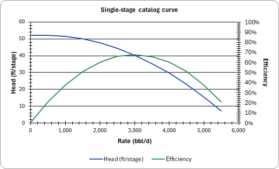
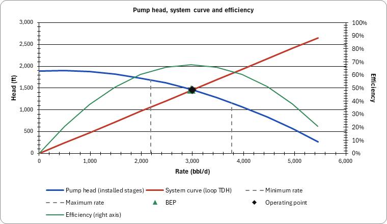
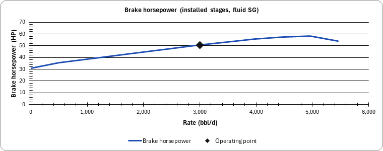
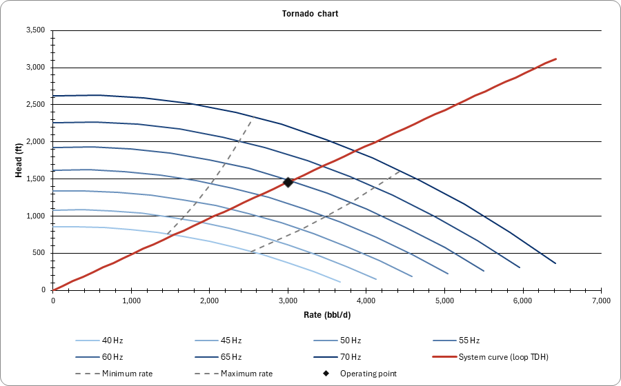
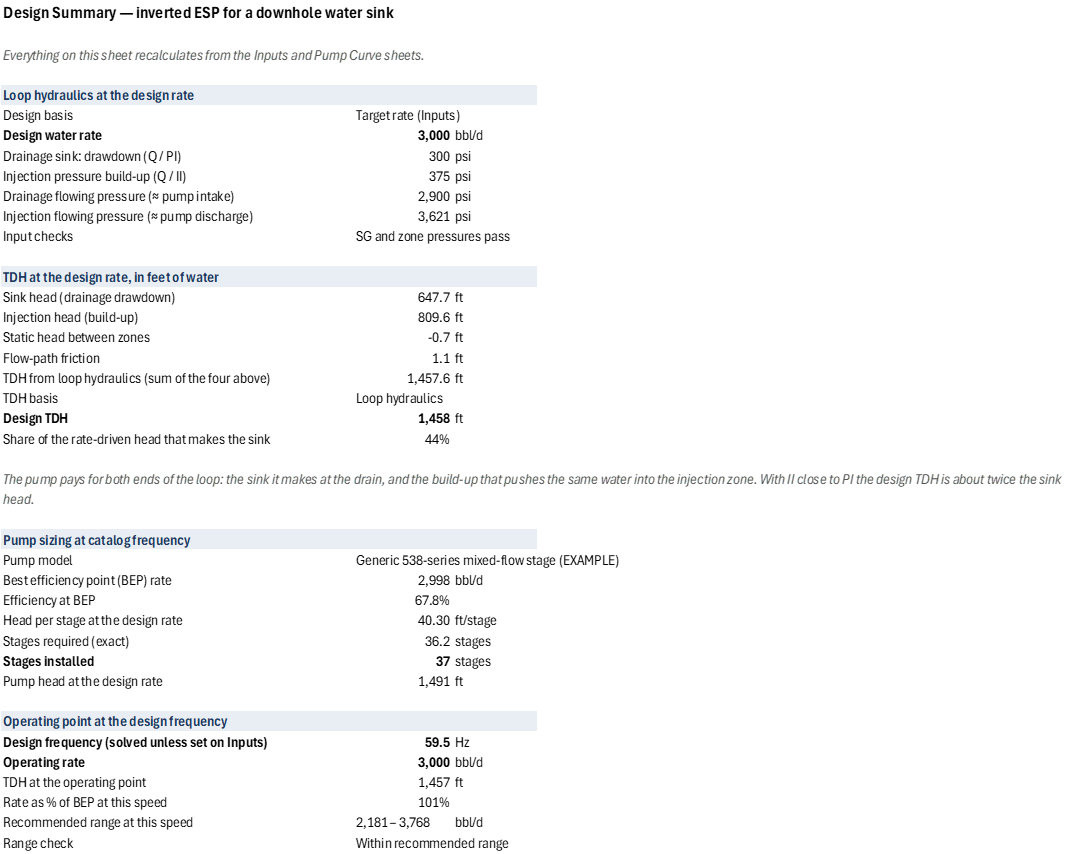
Design by rate, or by sink: enter the drawdown wanted at the drainage perforations and the design rate becomes PI × sink. From the loop hydraulics (or a known TDH) and a vendor single-stage curve it returns the design TDH, split in feet into sink head, injection head, static head and friction; the stage count, brake horsepower, BEP and operating-point efficiency; the sink at the operating point; the drive frequency that delivers each rate; motor loading, motor cooling velocity, packer differential and shaft thrust. With injectivity close to the PI the design TDH is about twice the sink head, because the pump also has to re-inject the water it drains. Two print-ready charts: the pump performance curve against the system curve, and the variable-speed (tornado) chart.
Two input checks: an SG outside the plausible brine range (a psi/ft gradient typed into the SG cell), and a static head between the zones that is not about zero (zone pressures and spacing that do not describe one connected aquifer). An injection static pressure of 0 is computed for the same-aquifer case.
The functions the PO.ESP.* catalog lacks are defined as workbook LAMBDAs:
PO.ESP.DWS.TDH, PO.ESP.Affinity.Rate, PO.ESP.Affinity.Head, PO.ESP.Affinity.Power,
PO.ESP.Curve.HeadAtSpeed, PO.ESP.Curve.PowerAtSpeed, PO.ESP.Motor.CoolingVelocity,
PO.ESP.Shaft.Thrust.
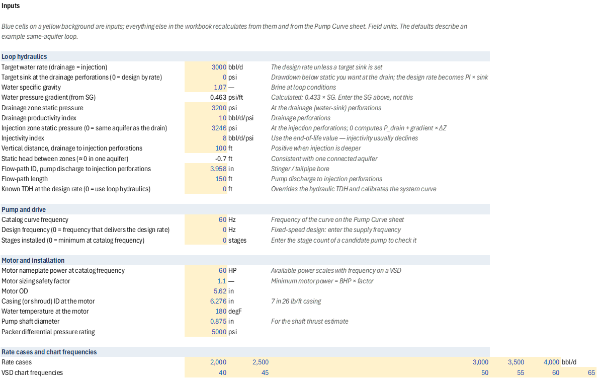
Inputs
Named cells you can edit — every result recalculates from them.
| Name | Description | Default | Unit |
|---|---|---|---|
DWS_Q |
Target water rate (drainage = injection) | 3000 | bbl/d |
DWS_Sink |
Target sink at the drainage perforations (0 = design by rate) | 0 | psi |
DWS_SG |
Water specific gravity | 1.07 | — |
DWS_Pdr |
Drainage zone static pressure | 3200 | psi |
DWS_PI |
Drainage productivity index | 10 | bbl/d/psi |
DWS_Pinj |
Injection zone static pressure (0 = same aquifer as the drain) | 3246 | psi |
DWS_II |
Injectivity index | 8 | bbl/d/psi |
DWS_dZ |
Vertical distance, drainage to injection perforations | 100 | ft |
DWS_FlowID |
Flow-path ID, pump discharge to injection perforations | 3.958 | in |
DWS_FlowL |
Flow-path length | 150 | ft |
DWS_TDHKnown |
Known TDH at the design rate (0 = use loop hydraulics) | 0 | ft |
DWS_Fbase |
Catalog curve frequency | 60 | Hz |
DWS_FreqSet |
Design frequency (0 = frequency that delivers the design rate) | 0 | Hz |
DWS_StagesSet |
Stages installed (0 = minimum at catalog frequency) | 0 | stages |
DWS_MotorHP |
Motor nameplate power at catalog frequency | 60 | HP |
DWS_SF |
Motor sizing safety factor | 1.10 | — |
DWS_MotorOD |
Motor OD | 5.62 | in |
DWS_CasingID |
Casing (or shroud) ID at the motor | 6.276 | in |
DWS_Temp |
Water temperature at the motor | 180 | degF |
DWS_Shaft |
Pump shaft diameter | 0.875 | in |
DWS_PackerRating |
Packer differential pressure rating | 5000 | psi |
DWS_Qmin |
Pump recommended range — minimum rate | 2200 | bbl/d |
DWS_Qmax |
Pump recommended range — maximum rate | 3800 | bbl/d |
DWS_Cases |
Rate cases (five) | 2000–4000 | bbl/d |
DWS_VsdF |
Tornado chart frequencies (seven) | 40–70 | Hz |
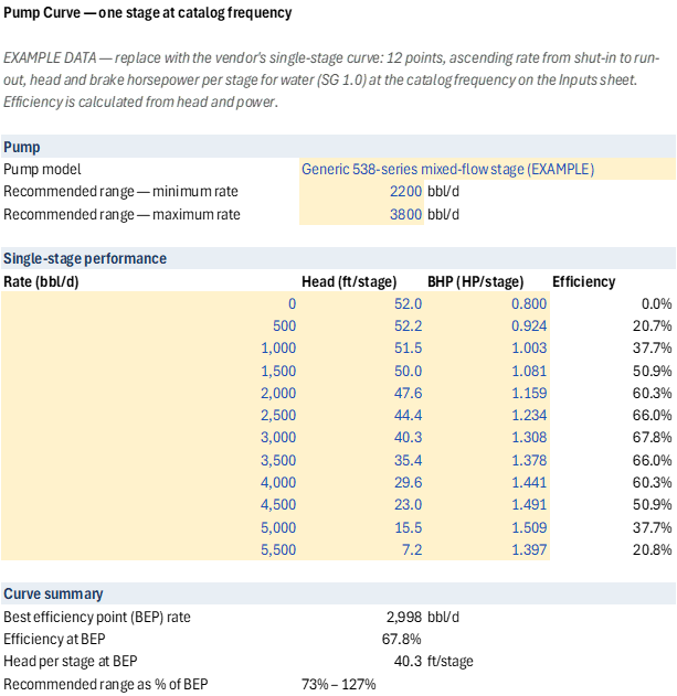
The single-stage curve (DWS_CurveQ, DWS_CurveH, DWS_CurveP) on the Pump Curve sheet is
example data to be replaced with the vendor's curve.
7 sheets, shown with the values the file opens with
| A | |
|---|---|
| 1 | Inverted ESP Sizing — Downhole Water Sink / Downhole Water Loop |
| 2 | |
| 3 | What this workbook does |
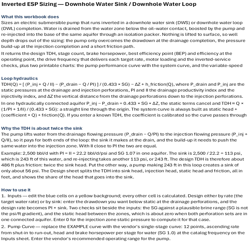
| 4 | Sizes an electric submersible pump that runs inverted in a downhole water sink (DWS) or downhole water loop (DWL) completion. Water is drained from the water zone below the oil–water contact, boosted by the pump and re-injected into the base of the same aquifer through an isolation packer. Nothing is lifted to surface, so well depth drops out of the sizing: the pump only overcomes the drawdown at the drainage completion, the pressure build-up at the injection completion and a short friction path. |
| 5 | It returns the design TDH, stage count, brake horsepower, best efficiency point (BEP) and efficiency at the operating point, the drive frequency that delivers each target rate, motor loading and the inverted-service checks, plus two printable charts: the pump performance curve with the system curve, and the variable-speed (tornado) chart. |
| 6 | |
| 7 | Loop hydraulics |
| 8 | TDH(Q) = [ (P_inj + Q / II) − (P_drain − Q / PI) ] / (0.433 × SG) − ΔZ + h_friction(Q), where P_drain and P_inj are the static pressures at the drainage and injection perforations, PI and II the drainage productivity index and the injectivity index, and ΔZ the vertical distance from the drainage perforations down to the injection perforations. |
| 9 | In one hydraulically connected aquifer P_inj − P_drain = 0.433 × SG × ΔZ, the static terms cancel and TDH ≈ Q × (1/PI + 1/II) / (0.433 × SG): a straight line through the origin. The system curve is always built as static head + (coefficient × Q) + friction(Q). If you enter a known TDH, the coefficient is calibrated so the curve passes through your TDH at the design rate. |
| 10 | |
| 11 | Why the TDH is about twice the sink |
| 12 | The pump lifts water from the drainage flowing pressure (P_drain − Q/PI) to the injection flowing pressure (P_inj + Q/II), so it pays for both ends of the loop: the sink it makes at the drain, and the build-up it needs to push the same water into the injection zone. With II close to PI the two are equal. |
| 13 | Example: 2,500 bbl/d with PI = II = 22.2 bbl/d/psi and SG 1.07 in one aquifer. The sink is 2,500 / 22.2 = 113 psi, which is 243 ft of this water, and re-injecting takes another 113 psi, or 243 ft. The design TDH is therefore about 486 ft plus friction: twice the sink head. Put the other way, a pump making 243 ft in this loop creates a sink of only about 56 psi. The Design sheet splits the TDH into sink head, injection head, static head and friction, all in feet, and shows the share of the head that goes into the sink. |
| 14 | |
| 15 | How to use it |
| 16 | 1. Inputs — edit the blue cells on a yellow background; every other cell is calculated. Design either by rate (the target water rate) or by sink: enter the drawdown you want below static at the drainage perforations, and the design rate becomes PI × sink. Two checks sit beside the inputs: the SG against a plausible brine range (SG is not the psi/ft gradient), and the static head between the zones, which is about zero when both perforation sets are in one connected aquifer. Enter 0 for the injection zone static pressure to compute it for that case. |
| 17 | 2. Pump Curve — replace the EXAMPLE curve with the vendor's single-stage curve: 12 points, ascending rate from shut-in to run-out, head and brake horsepower per stage for water (SG 1.0) at the catalog frequency on the Inputs sheet. Enter the vendor's recommended operating range for the pump. |
| 18 | 3. Design — the sizing summary. Stages are set at the catalog frequency and the drive frequency is then solved so the pump delivers exactly the design rate (or enter a design frequency on the Inputs sheet). The rate-case table shows the frequency, loading and range check for each rate case. |
| 19 | 4. Performance Chart and VSD Chart — both are set up to print on one page (File › Print). |
| 20 | |
| 21 | Choosing the sink |
| 22 | • A stronger sink is not always better. A drainage sink much stronger than the oil completion's drawdown pulls oil down into the water drain (reverse coning) and sends it to the injection zone; one too weak lets water cone up into the oil completion. The sinks that keep both completions clean form the inflow performance window of the downhole water sink literature (Wojtanowicz and co-workers). This workbook sizes the pump for the sink or rate you choose; it does not compute that window, so check the sink with a coning analysis or a near-well model first. |
| 23 | |
| 24 | Inverted-service notes |
| 25 | • Thrust: inverting the pump puts impeller weight against the hydraulic thrust. Prefer compression (fixed-impeller) stages, size the protector thrust bearing for the load on the Design sheet in both directions, and ask the vendor for the recommended operating range in inverted service. |
| 26 | • Motor cooling: with the motor on top, drainage water must flow down past it. Keep the annular velocity at 1 ft/s or more; if the motor sits in a dead leg, fit a shroud. |
| 27 | • Packer: the packer below the pump carries the pump differential pressure from below, plus start/stop surges. |
| 28 | • Injectivity: injectivity usually declines with oil carry-over and solids. Size for the end-of-life injectivity index, and stay below the injection zone fracture pressure. PI and II from separate tests ignore sink–source interference, which normally makes the computed head conservative. |
| 29 | • Gauges: the discharge sits below the intake, so a gauge-to-gauge pressure difference also includes the fluid column over the pump length. |
| 30 | |
| 31 | Requirements |
| 32 | The workbook calls Petroleum Office functions (PO.ESP.*) and defines eight LAMBDA functions (Formulas › Name Manager: PO.ESP.DWS.TDH, PO.ESP.Affinity.Rate/Head/Power, PO.ESP.Curve.HeadAtSpeed/PowerAtSpeed, PO.ESP.Motor.CoolingVelocity, PO.ESP.Shaft.Thrust). It opens with the example results already calculated; recalculating after an edit needs the Petroleum Office add-in and an Excel version with LAMBDA (Microsoft 365 or Excel 2024). |
| A | B | C | D | E | F | G | H | I | |
|---|---|---|---|---|---|---|---|---|---|
| 1 | Inputs | ||||||||
| 2 | Blue cells on a yellow background are inputs; everything else in the workbook recalculates from them and from the Pump Curve sheet. Field units. The defaults describe an example same-aquifer loop. | ||||||||
| 3 | |||||||||
| 4 | Loop hydraulics | ||||||||
| 5 | Target water rate (drainage = injection) | 3000 | bbl/d | The design rate unless a target sink is set | |||||
| 6 | Target sink at the drainage perforations (0 = design by rate) | 0 | psi | Drawdown below static you want at the drain; the design rate becomes PI × sink | |||||
| 7 | Water specific gravity | 1.07 | — | Brine at loop conditions | |||||
| 8 | Water pressure gradient (from SG) | 0.463 | psi/ft | Calculated: 0.433 × SG. Enter the SG above, not this | |||||
| 9 | Drainage zone static pressure | 3200 | psi | At the drainage (water-sink) perforations | |||||
| 10 | Drainage productivity index | 10 | bbl/d/psi | Drainage perforations | |||||
| 11 | Injection zone static pressure (0 = same aquifer as the drain) | 3246 | psi | At the injection perforations; 0 computes P_drain + gradient × ΔZ | |||||
| 12 | Injectivity index | 8 | bbl/d/psi | Use the end-of-life value — injectivity usually declines | |||||
| 13 | Vertical distance, drainage to injection perforations | 100 | ft | Positive when injection is deeper | |||||
| 14 | Static head between zones (≈ 0 in one aquifer) | -0.7 | ft | Consistent with one connected aquifer | |||||
| 15 | Flow-path ID, pump discharge to injection perforations | 3.958 | in | Stinger / tailpipe bore | |||||
| 16 | Flow-path length | 150 | ft | Pump discharge to injection perforations | |||||
| 17 | Known TDH at the design rate (0 = use loop hydraulics) | 0 | ft | Overrides the hydraulic TDH and calibrates the system curve | |||||
| 18 | |||||||||
| 19 | Pump and drive | ||||||||
| 20 | Catalog curve frequency | 60 | Hz | Frequency of the curve on the Pump Curve sheet | |||||
| 21 | Design frequency (0 = frequency that delivers the design rate) | 0 | Hz | Fixed-speed design: enter the supply frequency | |||||
| 22 | Stages installed (0 = minimum at catalog frequency) | 0 | stages | Enter the stage count of a candidate pump to check it | |||||
| 23 | |||||||||
| 24 | Motor and installation | ||||||||
| 25 | Motor nameplate power at catalog frequency | 60 | HP | Available power scales with frequency on a VSD | |||||
| 26 | Motor sizing safety factor | 1.1 | — | Minimum motor power = BHP × factor | |||||
| 27 | Motor OD | 5.62 | in | ||||||
| 28 | Casing (or shroud) ID at the motor | 6.276 | in | 7 in 26 lb/ft casing | |||||
| 29 | Water temperature at the motor | 180 | degF | ||||||
| 30 | Pump shaft diameter | 0.875 | in | For the shaft thrust estimate | |||||
| 31 | Packer differential pressure rating | 5000 | psi | ||||||
| 32 | |||||||||
| 33 | Rate cases and chart frequencies | ||||||||
| 34 | Rate cases | 2,000 | 2,500 | 3,000 | 3,500 | 4,000 | bbl/d | ||
| 35 | VSD chart frequencies | 40 | 45 | 50 | 55 | 60 | 65 | 70 | Hz |
| A | B | C | D | E | F | G | H | I | J | K | L | M | N | |
|---|---|---|---|---|---|---|---|---|---|---|---|---|---|---|
| 1 | Pump Curve — one stage at catalog frequency | |||||||||||||
| 2 | EXAMPLE DATA — replace with the vendor's single-stage curve: 12 points, ascending rate from shut-in to run-out, head and brake horsepower per stage for water (SG 1.0) at the catalog frequency on the Inputs sheet. Efficiency is calculated from head and power. | |||||||||||||
| 3 | ||||||||||||||
| 4 | Pump | |||||||||||||
| 5 | Pump model | Generic 538-series mixed-flow stage (EXAMPLE) | ||||||||||||
| 6 | Recommended range — minimum rate | 2200 | bbl/d | |||||||||||
| 7 | Recommended range — maximum rate | 3800 | bbl/d | |||||||||||
| 8 | ||||||||||||||
| 9 | Single-stage performance | |||||||||||||
| 10 | Rate (bbl/d) | Head (ft/stage) | BHP (HP/stage) | Efficiency | ||||||||||
| 11 | 0 | 52.0 | 0.800 | 0.0% | ||||||||||
| 12 | 500 | 52.2 | 0.924 | 20.7% | ||||||||||
| 13 | 1,000 | 51.5 | 1.003 | 37.7% | ||||||||||
| 14 | 1,500 | 50.0 | 1.081 | 50.9% | ||||||||||
| 15 | 2,000 | 47.6 | 1.159 | 60.3% | ||||||||||
| 16 | 2,500 | 44.4 | 1.234 | 66.0% | ||||||||||
| 17 | 3,000 | 40.3 | 1.308 | 67.8% | ||||||||||
| 18 | 3,500 | 35.4 | 1.378 | 66.0% | ||||||||||
| 19 | 4,000 | 29.6 | 1.441 | 60.3% | ||||||||||
| 20 | 4,500 | 23.0 | 1.491 | 50.9% | ||||||||||
| 21 | 5,000 | 15.5 | 1.509 | 37.7% | ||||||||||
| 22 | 5,500 | 7.2 | 1.397 | 20.8% | ||||||||||
| 23 | ||||||||||||||
| 24 | Curve summary | |||||||||||||
| 25 | Best efficiency point (BEP) rate | 2,998 | bbl/d | |||||||||||
| 26 | Efficiency at BEP | 67.8% | ||||||||||||
| 27 | Head per stage at BEP | 40.3 | ft/stage | |||||||||||
| 28 | Recommended range as % of BEP | 73% – 127% |
| A | B | C | D | E | F | G | H | |
|---|---|---|---|---|---|---|---|---|
| 1 | Design Summary — inverted ESP for a downhole water sink | |||||||
| 2 | Everything on this sheet recalculates from the Inputs and Pump Curve sheets. | |||||||
| 3 | ||||||||
| 4 | Loop hydraulics at the design rate | |||||||
| 5 | Design basis | Target rate (Inputs) | ||||||
| 6 | Design water rate | 3,000 | bbl/d | |||||
| 7 | Drainage sink: drawdown (Q / PI) | 300 | psi | |||||
| 8 | Injection pressure build-up (Q / II) | 375 | psi | |||||
| 9 | Drainage flowing pressure (≈ pump intake) | 2,900 | psi | |||||
| 10 | Injection flowing pressure (≈ pump discharge) | 3,621 | psi | |||||
| 11 | Input checks | SG and zone pressures pass | ||||||
| 12 | ||||||||
| 13 | TDH at the design rate, in feet of water | |||||||
| 14 | Sink head (drainage drawdown) | 647.7 | ft | |||||
| 15 | Injection head (build-up) | 809.6 | ft | |||||
| 16 | Static head between zones | -0.7 | ft | |||||
| 17 | Flow-path friction | 1.1 | ft | |||||
| 18 | TDH from loop hydraulics (sum of the four above) | 1,457.6 | ft | |||||
| 19 | TDH basis | Loop hydraulics | ||||||
| 20 | Design TDH | 1,458 | ft | |||||
| 21 | Share of the rate-driven head that makes the sink | 44% | ||||||
| 22 | The pump pays for both ends of the loop: the sink it makes at the drain, and the build-up that pushes the same water into the injection zone. With II close to PI the design TDH is about twice the sink head. | |||||||
| 23 | ||||||||
| 24 | Pump sizing at catalog frequency | |||||||
| 25 | Pump model | Generic 538-series mixed-flow stage (EXAMPLE) | ||||||
| 26 | Best efficiency point (BEP) rate | 2,998 | bbl/d | |||||
| 27 | Efficiency at BEP | 67.8% | ||||||
| 28 | Head per stage at the design rate | 40.30 | ft/stage | |||||
| 29 | Stages required (exact) | 36.2 | stages | |||||
| 30 | Stages installed | 37 | stages | |||||
| 31 | Pump head at the design rate | 1,491 | ft | |||||
| 32 | ||||||||
| 33 | Operating point at the design frequency | |||||||
| 34 | Design frequency (solved unless set on Inputs) | 59.5 | Hz | |||||
| 35 | Operating rate | 3,000 | bbl/d | |||||
| 36 | TDH at the operating point | 1,457 | ft | |||||
| 37 | Rate as % of BEP at this speed | 101% | ||||||
| 38 | Recommended range at this speed | 2,181 – 3,768 | bbl/d | |||||
| 39 | Range check | Within recommended range | ||||||
| 40 | Pump efficiency | 67.8% | ||||||
| 41 | Hydraulic horsepower | 34.3 | HP | |||||
| 42 | Brake horsepower | 50.6 | HP | |||||
| 43 | Pump differential pressure | 675 | psi | |||||
| 44 | Sink at the operating point (drainage drawdown) | 300 | psi | |||||
| 45 | ||||||||
| 46 | Motor | |||||||
| 47 | Minimum motor power (BHP × safety factor) | 55.7 | HP | |||||
| 48 | Motor power available at the design frequency | 59.5 | HP | |||||
| 49 | Motor load | 85% | ||||||
| 50 | Load status | Optimal loading | ||||||
| 51 | Velocity past the motor | 4.57 | ft/s | |||||
| 52 | Cooling check | OK (1 ft/s or more) | ||||||
| 53 | Estimated motor temperature | 193 | degF | |||||
| 54 | ||||||||
| 55 | Inverted-service checks | |||||||
| 56 | Packer differential (pump ΔP, acting from below) | 675 | psi | |||||
| 57 | Packer check | Within rating | ||||||
| 58 | Hydraulic thrust on the pump shaft | 406 | lbf | |||||
| 59 | Size the protector thrust bearing for this load in the inverted direction; compression (fixed-impeller) stages are preferred for inverted service. Confirm the recommended operating range for inverted service with the vendor. | |||||||
| 60 | ||||||||
| 61 | Rate cases (installed stages on a variable-speed drive) | |||||||
| 62 | Case | Rate (bbl/d) | TDH (ft) | Frequency (Hz) | % of BEP | Range check | BHP (HP) | Motor load |
| 63 | Design rate | 3,000 | 1,458 | 59.5 | 101% | Within range | 50.6 | 85% |
| 64 | Case 1 | 2,000 | 971 | 46.5 | 86% | Within range | 22.9 | 49% |
| 65 | Case 2 | 2,500 | 1,214 | 53.1 | 94% | Within range | 35.3 | 66% |
| 66 | Case 3 | 3,000 | 1,458 | 59.5 | 101% | Within range | 50.6 | 85% |
| 67 | Case 4 | 3,500 | 1,701 | 65.6 | 107% | Within range | 69.2 | 105% |
| 68 | Case 5 | 4,000 | 1,944 | 71.6 | 112% | Within range | 91.2 | 127% |
| A | B | C | D | E | F | G | H | I | |
|---|---|---|---|---|---|---|---|---|---|
| 1 | Pump performance — Generic 538-series mixed-flow stage (EXAMPLE) | ||||||||
| 2 | |||||||||
| 3 | Stages installed | 37 | Design frequency | 59.5 | Hz | ||||
| 4 | Operating rate | 3,000 | bbl/d | TDH at operating point | 1,457 | ft | |||
| 5 | Pump efficiency | 67.8% | Brake horsepower | 50.6 | HP | ||||
| 6 | BEP rate at this speed | 2,972 | bbl/d | Water specific gravity | 1.07 | ||||
| 7 | |||||||||
| 8 | |||||||||
| 9 | |||||||||
| 10 | |||||||||
| 11 | |||||||||
| 12 | |||||||||
| 13 | |||||||||
| 14 | |||||||||
| 15 | |||||||||
| 16 | |||||||||
| 17 | |||||||||
| 18 | |||||||||
| 19 | |||||||||
| 20 | |||||||||
| 21 | |||||||||
| 22 | |||||||||
| 23 | |||||||||
| 24 | |||||||||
| 25 | |||||||||
| 26 | |||||||||
| 27 | |||||||||
| 28 | |||||||||
| 29 | |||||||||
| 30 | |||||||||
| 31 | |||||||||
| 32 | |||||||||
| 33 | |||||||||
| 34 | |||||||||
| 35 | |||||||||
| 36 | |||||||||
| 37 | |||||||||
| 38 | |||||||||
| 39 | |||||||||
| 40 | |||||||||
| 41 | |||||||||
| 42 | |||||||||
| 43 | |||||||||
| 44 | |||||||||
| 45 |
| A | |
|---|---|
| 1 | Variable-speed performance — 37 stages, Generic 538-series mixed-flow stage (EXAMPLE) |
| 2 | Pump head for the installed stages at each drive frequency (affinity laws: rate ∝ f, head ∝ f², power ∝ f³). Dashed lines bound the recommended operating range; the red line is the loop system curve. |
| 3 | |
| 4 | |
| 5 | |
| 6 | |
| 7 | |
| 8 | |
| 9 | |
| 10 | |
| 11 | |
| 12 | |
| 13 | |
| 14 | |
| 15 | |
| 16 | |
| 17 | |
| 18 | |
| 19 | |
| 20 | |
| 21 | |
| 22 | |
| 23 | |
| 24 | |
| 25 | |
| 26 | |
| 27 | |
| 28 | |
| 29 | |
| 30 | |
| 31 |
| A | B | C | D | E | F | G | H | I | J | K | L | M | N | O | |
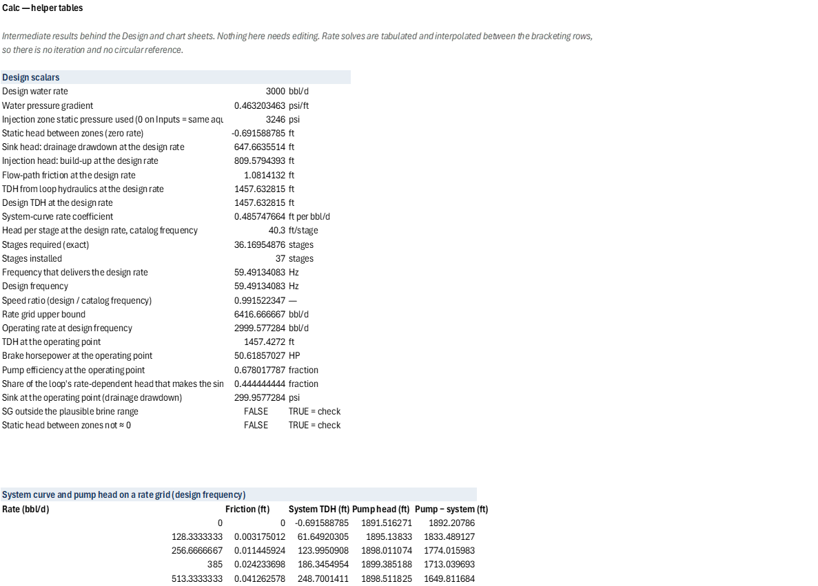
|---|---|---|---|---|---|---|---|---|---|---|---|---|---|---|---|
| 1 | Calc — helper tables | ||||||||||||||
| 2 | Intermediate results behind the Design and chart sheets. Nothing here needs editing. Rate solves are tabulated and interpolated between the bracketing rows, so there is no iteration and no circular reference. | ||||||||||||||
| 3 | |||||||||||||||
| 4 | Design scalars | ||||||||||||||
| 5 | Design water rate | 3000 | bbl/d | ||||||||||||
| 6 | Water pressure gradient | 0.4632034632 | psi/ft | ||||||||||||
| 7 | Injection zone static pressure used (0 on Inputs = same aquifer) | 3246 | psi | ||||||||||||
| 8 | Static head between zones (zero rate) | -0.691588785 | ft | ||||||||||||
| 9 | Sink head: drainage drawdown at the design rate | 647.6635514 | ft | ||||||||||||
| 10 | Injection head: build-up at the design rate | 809.5794393 | ft | ||||||||||||
| 11 | Flow-path friction at the design rate | 1.0814132 | ft | ||||||||||||
| 12 | TDH from loop hydraulics at the design rate | 1457.632815 | ft | ||||||||||||
| 13 | Design TDH at the design rate | 1457.632815 | ft | ||||||||||||
| 14 | System-curve rate coefficient | 0.4857476636 | ft per bbl/d | ||||||||||||
| 15 | Head per stage at the design rate, catalog frequency | 40.3 | ft/stage | ||||||||||||
| 16 | Stages required (exact) | 36.16954876 | stages | ||||||||||||
| 17 | Stages installed | 37 | stages | ||||||||||||
| 18 | Frequency that delivers the design rate | 59.49134083 | Hz | ||||||||||||
| 19 | Design frequency | 59.49134083 | Hz | ||||||||||||
| 20 | Speed ratio (design / catalog frequency) | 0.9915223472 | — | ||||||||||||
| 21 | Rate grid upper bound | 6416.666667 | bbl/d | ||||||||||||
| 22 | Operating rate at design frequency | 2999.577284 | bbl/d | ||||||||||||
| 23 | TDH at the operating point | 1457.4272 | ft | ||||||||||||
| 24 | Brake horsepower at the operating point | 50.61857027 | HP | ||||||||||||
| 25 | Pump efficiency at the operating point | 0.6780177872 | fraction | ||||||||||||
| 26 | Share of the loop's rate-dependent head that makes the sink | 0.4444444444 | fraction | ||||||||||||
| 27 | Sink at the operating point (drainage drawdown) | 299.9577284 | psi | ||||||||||||
| 28 | SG outside the plausible brine range | FALSE | TRUE = check | ||||||||||||
| 29 | Static head between zones not ≈ 0 | FALSE | TRUE = check | ||||||||||||
| 30 | |||||||||||||||
| 31 | |||||||||||||||
| 32 | |||||||||||||||
| 33 | |||||||||||||||
| 34 | System curve and pump head on a rate grid (design frequency) | ||||||||||||||
| 35 | Rate (bbl/d) | Friction (ft) | System TDH (ft) | Pump head (ft) | Pump − system (ft) | ||||||||||
| 36 | 0 | 0 | -0.691588785 | 1891.516271 | 1892.20786 | ||||||||||
| 37 | 128.3333333 | 0.003175012017 | 61.64920305 | 1895.13833 | 1833.489127 | ||||||||||
| 38 | 256.6666667 | 0.0114459242 | 123.9950908 | 1898.011074 | 1774.015983 | ||||||||||
| 39 | 385 | 0.02423369818 | 186.3454954 | 1899.385188 | 1713.039693 | ||||||||||
| 40 | 513.3333333 | 0.04126257791 | 248.7001411 | 1898.511825 | 1649.811684 | ||||||||||
| 41 | 641.6666667 | 0.06235049152 | 311.0588458 | 1894.90692 | 1583.848074 | ||||||||||
| 42 | 770 | 0.08736252678 | 373.4214747 | 1888.793164 | 1515.37169 | ||||||||||
| 43 | 898.3333333 | 0.1161921392 | 435.7879211 | 1880.509903 | 1444.721982 | ||||||||||
| 44 | 1026.666667 | 0.1487516697 | 498.1580975 | 1870.394531 | 1372.236434 | ||||||||||
| 45 | 1155 | 0.1849668991 | 560.5319295 | 1858.596268 | 1298.064338 | ||||||||||
| 46 | 1283.333333 | 0.2247736373 | 622.9093531 | 1844.921934 | 1222.012581 | ||||||||||
| 47 | 1411.666667 | 0.2681154502 | 685.2903117 | 1829.142054 | 1143.851743 | ||||||||||
| 48 | 1540 | 0.3149420707 | 747.6747552 | 1811.032111 | 1063.357356 | ||||||||||
| 49 | 1668.333333 | 0.3652082463 | 810.0626382 | 1790.548723 | 980.4860845 | ||||||||||
| 50 | 1796.666667 | 0.4188728767 | 872.4539196 | 1767.877231 | 895.4233112 | ||||||||||
| 51 | 1925 | 0.475898354 | 934.8485619 | 1743.217621 | 808.3690588 | ||||||||||
| 52 | 2053.333333 | 0.5362500446 | 997.2465304 | 1716.759147 | 719.5126163 | ||||||||||
| 53 | 2181.666667 | 0.5998958782 | 1059.647793 | 1688.491855 | 628.8440616 | ||||||||||
| 54 | 2310 | 0.6668060136 | 1122.05232 | 1658.229907 | 536.1775865 | ||||||||||
| 55 | 2438.333333 | 0.7369525657 | 1184.460083 | 1625.781421 | 441.3213375 | ||||||||||
| 56 | 2566.666667 | 0.8103093784 | 1246.871057 | 1590.974885 | 344.103828 | ||||||||||
| 57 | 2695 | 0.8868518344 | 1309.285216 | 1553.860775 | 244.5755583 | ||||||||||
| 58 | 2823.333333 | 0.966556694 | 1371.702538 | 1514.626058 | 142.9235199 | ||||||||||
| 59 | 2951.666667 | 1.049401958 | 1434.123 | 1473.459694 | 39.33669365 | ||||||||||
| 60 | 3080 | 1.135366748 | 1496.546582 | 1430.516046 | -66.03053579 | ||||||||||
| 61 | 3208.333333 | 1.224431206 | 1558.973263 | 1385.710779 | -173.2624839 | ||||||||||
| 62 | 3336.666667 | 1.316576404 | 1621.403025 | 1338.858874 | -282.5441511 | ||||||||||
| 63 | 3465 | 1.411784265 | 1683.83585 | 1289.774957 | -394.060893 | ||||||||||
| 64 | 3593.333333 | 1.510037496 | 1746.27172 | 1238.326388 | -507.945332 | ||||||||||
| 65 | 3721.666667 | 1.611319525 | 1808.710619 | 1184.619473 | -624.0911451 | ||||||||||
| 66 | 3850 | 1.715614447 | 1871.15253 | 1128.828165 | -742.3243657 | ||||||||||
| 67 | 3978.333333 | 1.822906976 | 1933.59744 | 1071.126372 | -862.4710677 | ||||||||||
| 68 | 4106.666667 | 1.933182403 | 1996.045332 | 1011.621188 | -984.4241435 | ||||||||||
| 69 | 4235 | 2.046426553 | 2058.496193 | 950.2184775 | -1108.277715 | ||||||||||
| 70 | 4363.333333 | 2.162625751 | 2120.950009 | 886.7863739 | -1234.163635 | ||||||||||
| 71 | 4491.666667 | 2.281766793 | 2183.406767 | 821.1932353 | -1362.213532 | ||||||||||
| 72 | 4620 | 2.403836913 | 2245.866454 | 753.3398361 | -1492.526618 | ||||||||||
| 73 | 4748.333333 | 2.528823758 | 2308.329057 | 683.1930499 | -1625.136007 | ||||||||||
| 74 | 4876.666667 | 2.656715363 | 2370.794566 | 610.7278022 | -1760.066764 | ||||||||||
| 75 | 5005 | 2.787500131 | 2433.262967 | 535.9243539 | -1897.338613 | ||||||||||
| 76 | 5133.333333 | 2.921166809 | 2495.734251 | 459.0136681 | -2036.720583 | ||||||||||
| 77 | 5261.666667 | 3.057704472 | 2558.208405 | 380.5798983 | -2177.628507 | ||||||||||
| 78 | 5390 | 3.197102504 | 2620.68542 | 301.2337891 | -2319.451631 | ||||||||||
| 79 | 5518.333333 | 3.339350585 | 2683.165285 | 0 | -2683.165285 | ||||||||||
| 80 | 5646.666667 | 3.484438671 | 2745.64799 | 0 | -2745.64799 | ||||||||||
| 81 | 5775 | 3.632356984 | 2808.133525 | 0 | -2808.133525 | ||||||||||
| 82 | 5903.333333 | 3.783095999 | 2870.621881 | 0 | -2870.621881 | ||||||||||
| 83 | 6031.666667 | 3.936646432 | 2933.113048 | 0 | -2933.113048 | ||||||||||
| 84 | 6160 | 4.092999226 | 2995.607018 | 0 | -2995.607018 | ||||||||||
| 85 | 6288.333333 | 4.252145546 | 3058.103781 | 0 | -3058.103781 | ||||||||||
| 86 | 6416.666667 | 4.414076763 | 3120.603329 | 0 | -3120.603329 | ||||||||||
| 87 | |||||||||||||||
| 88 | Crossing index (last row with pump head above system) | 24 | |||||||||||||
| 89 | |||||||||||||||
| 90 | Frequency that delivers each rate (installed stages) | ||||||||||||||
| 91 | Design | Case 1 | Case 2 | Case 3 | Case 4 | Case 5 | |||||||||
| 92 | Rate (bbl/d) | 3000 | 2000 | 2500 | 3000 | 3500 | 4000 | ||||||||
| 93 | System TDH (ft) | 1457.632815 | 971.3145053 | 1214.449373 | 1457.632815 | 1700.863513 | 1944.140381 | ||||||||
| 94 | Frequency (Hz) | Pump head at the rate (ft) | |||||||||||||
| 95 | 30 | 0 | 273.8 | 143.375 | 0 | 0 | 0 | ||||||||
| 96 | 31 | 0 | 307.9304925 | 178.0141427 | 0 | 0 | 0 | ||||||||
| 97 | 32 | 0 | 343.1719637 | 213.6294763 | 0 | 0 | 0 | ||||||||
| 98 | 33 | 89.19404125 | 379.4845278 | 250.2322298 | 89.19404125 | 0 | 0 | ||||||||
| 99 | 34 | 126.8048654 | 416.8329919 | 287.8341529 | 126.8048654 | 0 | 0 | ||||||||
| 100 | 35 | 166.0029578 | 455.1896687 | 326.4664521 | 166.0029578 | 0 | 0 | ||||||||
| 101 | 36 | 206.46 | 494.5632235 | 366.1699128 | 206.46 | 0 | 0 | ||||||||
| 102 | 37 | 247.9298196 | 534.9797609 | 406.9811226 | 247.9298196 | 0 | 0 | ||||||||
| 103 | 38 | 290.3738551 | 576.4628433 | 448.9314197 | 290.3738551 | 0 | 0 | ||||||||
| 104 | 39 | 333.80176 | 619.0336163 | 492.0175913 | 333.80176 | 143.0472358 | 0 | ||||||||
| 105 | 40 | 378.2222222 | 662.7111111 | 536.2061932 | 378.2222222 | 187.6392798 | 0 | ||||||||
| 106 | 41 | 423.6482372 | 707.5071481 | 581.4657478 | 423.6482372 | 233.7199923 | 0 | ||||||||
| 107 | 42 | 470.1116911 | 753.4115166 | 627.7677755 | 470.1116911 | 281.015 | 0 | ||||||||
| 108 | 43 | 517.646419 | 800.4098506 | 675.0864686 | 517.646419 | 329.3155958 | 0 | ||||||||
| 109 | 44 | 566.2831803 | 848.4890902 | 723.4096282 | 566.2831803 | 378.5889667 | 158.5671844 | ||||||||
| 110 | 45 | 616.05 | 897.6373367 | 772.7550367 | 616.05 | 428.8435751 | 208.4260854 | ||||||||
| 111 | 46 | 666.9632252 | 947.8437255 | 823.1435109 | 666.9632252 | 480.0871474 | 259.9589603 | ||||||||
| 112 | 47 | 719.0016344 | 999.0983171 | 874.5940957 | 719.0016344 | 532.3269191 | 312.9087967 | ||||||||
| 113 | 48 | 772.1369182 | 1051.392 | 927.1242492 | 772.1369182 | 585.5793075 | 367.04 | ||||||||
| 114 | 49 | 826.3430786 | 1104.719044 | 980.7500043 | 826.3430786 | 639.8742462 | 422.1714348 | ||||||||
| 115 | 50 | 881.5961973 | 1159.084517 | 1035.486111 | 881.5961973 | 695.2405268 | 478.2745473 | ||||||||
| 116 | 51 | 937.8742317 | 1214.495623 | 1091.341859 | 937.8742317 | 751.7046829 | 535.3568687 | ||||||||
| 117 | 52 | 995.1580358 | 1270.959012 | 1148.308937 | 995.1580358 | 809.2912066 | 593.425351 | ||||||||
| 118 | 53 | 1053.449695 | 1328.480832 | 1206.375521 | 1053.449695 | 868.0217394 | 652.4864216 | ||||||||
| 119 | 54 | 1112.767253 | 1387.066775 | 1265.53066 | 1112.767253 | 927.8936876 | 712.5471912 | ||||||||
| 120 | 55 | 1173.127922 | 1446.722121 | 1325.764204 | 1173.127922 | 988.8824258 | 773.6274898 | ||||||||
| 121 | 56 | 1234.547683 | 1507.45177 | 1387.066722 | 1234.547683 | 1050.964139 | 835.7541174 | ||||||||
| 122 | 57 | 1297.041397 | 1569.260281 | 1449.429451 | 1297.041397 | 1114.116682 | 898.9521311 | ||||||||
| 123 | 58 | 1360.6229 | 1632.151896 | 1512.844228 | 1360.6229 | 1178.319439 | 963.2448596 | ||||||||
| 124 | 59 | 1425.305088 | 1696.130572 | 1577.303444 | 1425.305088 | 1243.553191 | 1028.65405 | ||||||||
| 125 | 60 | 1491.1 | 1761.2 | 1642.8 | 1491.1 | 1309.8 | 1095.2 | ||||||||
| 126 | 61 | 1558.015285 | 1827.362514 | 1709.329378 | 1558.015285 | 1377.048589 | 1162.894707 | ||||||||
| 127 | 62 | 1626.043937 | 1894.615904 | 1776.895692 | 1626.043937 | 1445.309997 | 1231.72197 | ||||||||
| 128 | 63 | 1695.175912 | 1962.957021 | 1845.504843 | 1695.175912 | 1514.599872 | 1301.659869 | ||||||||
| 129 | 64 | 1765.401792 | 2032.382911 | 1915.162367 | 1765.401792 | 1584.932885 | 1372.687855 | ||||||||
| 130 | 65 | 1836.71274 | 2102.890803 | 1985.873456 | 1836.71274 | 1656.322803 | 1444.786641 | ||||||||
| 131 | 66 | 1909.100453 | 2174.478094 | 2057.642991 | 1909.100453 | 1728.782561 | 1517.938111 | ||||||||
| 132 | 67 | 1982.557125 | 2247.142334 | 2130.475557 | 1982.557125 | 1802.324318 | 1592.125231 | ||||||||
| 133 | 68 | 2057.075408 | 2320.881222 | 2204.375473 | 2057.075408 | 1876.959521 | 1667.331967 | ||||||||
| 134 | 69 | 2132.648382 | 2395.692585 | 2279.346806 | 2132.648382 | 1952.698952 | 1743.543599 | ||||||||
| 135 | 70 | 2209.269521 | 2471.574378 | 2355.393391 | 2209.269521 | 2029.552778 | 1820.758675 | ||||||||
| 136 | 71 | 2286.932665 | 2548.52467 | 2432.518846 | 2286.932665 | 2107.527499 | 1898.990599 | ||||||||
| 137 | 72 | 2365.632 | 2626.541636 | 2510.726591 | 2365.632 | 2186.617063 | 1978.252894 | ||||||||
| 138 | 73 | 2445.363798 | 2705.623553 | 2590.019854 | 2445.363798 | 2266.812738 | 2058.558345 | ||||||||
| 139 | 74 | 2526.13152 | 2785.76879 | 2670.401693 | 2526.13152 | 2348.106267 | 2139.919044 | ||||||||
| 140 | 75 | 2607.940164 | 2866.975804 | 2751.875 | 2607.940164 | 2430.489834 | 2222.346438 | ||||||||
| 141 | |||||||||||||||
| 142 | Crossing index | 30 | 17 | 24 | 30 | 36 | 42 | ||||||||
| 143 | Required frequency (Hz) | 59.5 | 46.5 | 53.1 | 59.5 | 65.6 | 71.6 | ||||||||
| 144 | |||||||||||||||
| 145 | Pump curve at design frequency (installed stages) | ||||||||||||||
| 146 | Rate (bbl/d) | Head (ft) | BHP (HP) | Efficiency | System TDH (ft) | ||||||||||
| 147 | 0 | 1891.516271 | 30.8732969 | 0 | -0.691588785 | ||||||||||
| 148 | 495.7611736 | 1898.791334 | 35.65865792 | 0.2072182846 | 240.1619306 | ||||||||||
| 149 | 991.5223472 | 1873.328615 | 38.70739599 | 0.3766741649 | 481.0775435 | ||||||||||
| 150 | 1487.283521 | 1818.765645 | 41.71754244 | 0.5089734254 | 722.0481945 | ||||||||||
| 151 | 1983.044694 | 1731.464894 | 44.72768889 | 0.6025776932 | 963.0705235 | ||||||||||
| 152 | 2478.805868 | 1615.063893 | 47.62206047 | 0.6598836336 | 1204.142312 | ||||||||||
| 153 | 2974.567042 | 1465.92511 | 50.47784044 | 0.6780755657 | 1445.261916 | ||||||||||
| 154 | 3470.328215 | 1287.686077 | 53.17925392 | 0.6596014883 | 1686.428037 | ||||||||||
| 155 | 3966.089389 | 1076.709262 | 55.61052605 | 0.6027639353 | 1927.639607 | ||||||||||
| 156 | 4461.850563 | 836.6321969 | 57.5401071 | 0.5092396892 | 2168.895722 | ||||||||||
| 157 | 4957.611736 | 563.8173501 | 58.23475628 | 0.3767662571 | 2410.195599 | ||||||||||
| 158 | 5453.37291 | 261.9022529 | 53.91249472 | 0.2079497094 | 2651.538552 | ||||||||||
| 159 | |||||||||||||||
| 160 | Chart markers | ||||||||||||||
| 161 | Rate (bbl/d) | Head (ft) | BHP (HP) | Efficiency | |||||||||||
| 162 | Operating point | 2999.577284 | 1457.4272 | 50.61857027 | 0.6780177872 | ||||||||||
| 163 | Minimum rate, axis | 2181.349164 | 0 | ||||||||||||
| 164 | Minimum rate, on the pump curve | 2181.349164 | 1688.564172 | ||||||||||||
| 165 | Maximum rate, axis | 3767.784919 | 0 | ||||||||||||
| 166 | Maximum rate, on the pump curve | 3767.784919 | 1164.801003 | ||||||||||||
| 167 | BEP at design frequency | 2972.088236 | 1466.743322 | ||||||||||||
| 168 | |||||||||||||||
| 169 | Tornado chart — installed stages across drive frequencies | ||||||||||||||
| 170 | 40 Hz | 45 Hz | 50 Hz | 55 Hz | 60 Hz | 65 Hz | 70 Hz | ||||||||
| 171 | Rate | Head | Rate | Head | Rate | Head | Rate | Head | Rate | Head | Rate | Head | Rate | Head | |
| 172 | 0 | 855.1111111 | 0 | 1082.25 | 0 | 1336.111111 | 0 | 1616.694444 | 0 | 1924 | 0 | 2258.027778 | 0 | 2618.777778 | |
| 173 | 333.3333333 | 858.4 | 375 | 1086.4125 | 416.6666667 | 1341.25 | 458.3333333 | 1622.9125 | 500 | 1931.4 | 541.6666667 | 2266.7125 | 583.3333333 | 2628.85 | |
| 174 | 666.6666667 | 846.8888889 | 750 | 1071.84375 | 833.3333333 | 1323.263889 | 916.6666667 | 1601.149306 | 1000 | 1905.5 | 1083.333333 | 2236.315972 | 1166.666667 | 2593.597222 | |
| 175 | 1000 | 822.2222222 | 1125 | 1040.625 | 1250 | 1284.722222 | 1375 | 1554.513889 | 1500 | 1850 | 1625 | 2171.180556 | 1750 | 2518.055556 | |
| 176 | 1333.333333 | 782.7555556 | 1500 | 990.675 | 1666.666667 | 1223.055556 | 1833.333333 | 1479.897222 | 2000 | 1761.2 | 2166.666667 | 2066.963889 | 2333.333333 | 2397.188889 | |
| 177 | 1666.666667 | 730.1333333 | 1875 | 924.075 | 2083.333333 | 1140.833333 | 2291.666667 | 1380.408333 | 2500 | 1642.8 | 2708.333333 | 1928.008333 | 2916.666667 | 2236.033333 | |
| 178 | 2000 | 662.7111111 | 2250 | 838.74375 | 2500 | 1035.486111 | 2750 | 1252.938194 | 3000 | 1491.1 | 3250 | 1749.971528 | 3500 | 2029.552778 | |
| 179 | 2333.333333 | 582.1333333 | 2625 | 736.7625 | 2916.666667 | 909.5833333 | 3208.333333 | 1100.595833 | 3500 | 1309.8 | 3791.666667 | 1537.195833 | 4083.333333 | 1782.783333 | |
| 180 | 2666.666667 | 486.7555556 | 3000 | 616.05 | 3333.333333 | 760.5555556 | 3666.666667 | 920.2722222 | 4000 | 1095.2 | 4333.333333 | 1285.338889 | 4666.666667 | 1490.688889 | |
| 181 | 3000 | 378.2222222 | 3375 | 478.6875 | 3750 | 590.9722222 | 4125 | 715.0763889 | 4500 | 851 | 4875 | 998.7430556 | 5250 | 1158.305556 | |
| 182 | 3333.333333 | 254.8888889 | 3750 | 322.59375 | 4166.666667 | 398.2638889 | 4583.333333 | 481.8993056 | 5000 | 573.5 | 5416.666667 | 673.0659722 | 5833.333333 | 780.5972222 | |
| 183 | 3666.666667 | 118.4 | 4125 | 149.85 | 4583.333333 | 185 | 5041.666667 | 223.85 | 5500 | 266.4 | 5958.333333 | 312.65 | 6416.666667 | 362.6 | |
| 184 | |||||||||||||||
| 185 | Recommended-range boundaries across frequencies | ||||||||||||||
| 186 | Frequency (Hz) | Minimum rate | Head at minimum | Maximum rate | Head at maximum | ||||||||||
| 187 | 40 | 1466.666667 | 763.361123 | 2533.333333 | 526.5798109 | ||||||||||
| 188 | 45 | 1650 | 966.1289213 | 2850 | 666.4525731 | ||||||||||
| 189 | 50 | 1833.333333 | 1192.751755 | 3166.666667 | 822.7809545 | ||||||||||
| 190 | 55 | 2016.666667 | 1443.229623 | 3483.333333 | 995.5649549 | ||||||||||
| 191 | 60 | 2200 | 1717.562527 | 3800 | 1184.804574 | ||||||||||
| 192 | 65 | 2383.333333 | 2015.750465 | 4116.666667 | 1390.499813 | ||||||||||
| 193 | 70 | 2566.666667 | 2337.793439 | 4433.333333 | 1612.650671 |
| Name | Refers To | Comment |
|---|---|---|
| PO.ESP.Affinity.Head | =LAMBDA(h, f, f_base, h*(f/f_base)^2) | |
| PO.ESP.Affinity.Power | =LAMBDA(p, f, f_base, p*(f/f_base)^3) | |
| PO.ESP.Affinity.Rate | =LAMBDA(q, f, f_base, q*f/f_base) | |
| PO.ESP.Curve.HeadAtSpeed | =LAMBDA(q, f, f_base, curve_q, curve_head, IF(q*f_base/f>MAX(curve_q), 0, PO.ESP.Affinity.Head(PO.ESP.Curve.Head(q*f_base/f, curve_q, curve_head), f, f_base))) | |
| PO.ESP.Curve.PowerAtSpeed | =LAMBDA(q, f, f_base, curve_q, curve_hp, IF(q*f_base/f>MAX(curve_q), NA(), PO.ESP.Affinity.Power(PO.ESP.Curve.Power(q*f_base/f, curve_q, curve_hp), f, f_base))) | |
| PO.ESP.DWS.TDH | =LAMBDA(q, p_drain, pi_drain, p_inj, ii_inj, dz, sg, h_fric, PO.ESP.Head.FromPressure((p_inj + q/ii_inj) - (p_drain - q/pi_drain), sg) - dz + h_fric) | |
| PO.ESP.Motor.CoolingVelocity | =LAMBDA(q, casing_id, motor_od, 0.0119*q/(casing_id^2 - motor_od^2)) | |
| PO.ESP.Shaft.Thrust | =LAMBDA(dp, d_shaft, dp*PI()/4*d_shaft^2) | |
| DWS_BHPop | Calc!$B$24 | |
| DWS_Cases | Inputs!$B$34:$F$34 | |
| DWS_CasingID | Inputs!$B$28 | |
| DWS_CurveEff | 'Pump Curve'!$D$11:$D$22 | |
| DWS_CurveH | 'Pump Curve'!$B$11:$B$22 | |
| DWS_CurveP | 'Pump Curve'!$C$11:$C$22 | |
| DWS_CurveQ | 'Pump Curve'!$A$11:$A$22 | |
| DWS_EffBEP | 'Pump Curve'!$B$26 | |
| DWS_EffOp | Calc!$B$25 | |
| DWS_F | Calc!$B$19 | |
| DWS_FTarget | Calc!$B$18 | |
| DWS_Fbase | Inputs!$B$20 | |
| DWS_FlowID | Inputs!$B$15 | |
| DWS_FlowL | Inputs!$B$16 | |
| DWS_FreqSet | Inputs!$B$21 | |
| DWS_Grad | Calc!$B$6 | |
| DWS_GridTop | Calc!$B$21 | |
| DWS_HInj | Calc!$B$10 | |
| DWS_HSink | Calc!$B$9 | |
| DWS_HStgT | Calc!$B$15 | |
| DWS_HfT | Calc!$B$11 | |
| DWS_Hst | Calc!$B$8 | |
| DWS_HstFlag | Calc!$B$29 | |
| DWS_II | Inputs!$B$12 | |
| DWS_Kq | Calc!$B$14 | |
| DWS_MotorHP | Inputs!$B$25 | |
| DWS_MotorOD | Inputs!$B$27 | |
| DWS_N | Calc!$B$17 | |
| DWS_PI | Inputs!$B$10 | |
| DWS_PackerRating | Inputs!$B$31 | |
| DWS_Pdr | Inputs!$B$9 | |
| DWS_Pinj | Inputs!$B$11 | |
| DWS_PinjSt | Calc!$B$7 | |
| DWS_PumpModel | 'Pump Curve'!$B$5 | |
| DWS_Q | Inputs!$B$5 | |
| DWS_QBEP | 'Pump Curve'!$B$25 | |
| DWS_Qd | Calc!$B$5 | |
| DWS_Qmax | 'Pump Curve'!$B$7 | |
| DWS_Qmin | 'Pump Curve'!$B$6 | |
| DWS_Qop | Calc!$B$22 | |
| DWS_R | Calc!$B$20 | |
| DWS_SF | Inputs!$B$26 | |
| DWS_SG | Inputs!$B$7 | |
| DWS_SGFlag | Calc!$B$28 | |
| DWS_Shaft | Inputs!$B$30 | |
| DWS_Sink | Inputs!$B$6 | |
| DWS_SinkOp | Calc!$B$27 | |
| DWS_SinkShare | Calc!$B$26 | |
| DWS_StagesReq | Calc!$B$16 | |
| DWS_StagesSet | Inputs!$B$22 | |
| DWS_TDH | Calc!$B$13 | |
| DWS_TDHKnown | Inputs!$B$17 | |
| DWS_TDHLoop | Calc!$B$12 | |
| DWS_TDHop | Calc!$B$23 | |
| DWS_Temp | Inputs!$B$29 | |
| DWS_VsdF | Inputs!$B$35:$H$35 | |
| DWS_dZ | Inputs!$B$13 |
| Opens in | Needs the Petroleum Office add-in: its PO functions show #NAME? without it once Excel recalculates. |
| Functions used | PO.ESP.Curve.BEPPO.ESP.Curve.BEP.EffPO.ESP.Curve.EfficiencyPO.ESP.Curve.HeadPO.ESP.Curve.InRangePO.ESP.Curve.PowerPO.ESP.Head.FromPressurePO.ESP.Head.ToPressurePO.ESP.HydraulicHPPO.ESP.Motor.Load.StatusPO.ESP.Motor.LoadFactorPO.ESP.Motor.RequiredHPPO.ESP.Motor.Temp.RisePO.ESP.Nodal.DrawdownPO.ESP.Pump.EfficiencyPO.ESP.Pump.TotalHeadPO.ESP.StagesPO.ESP.Stages.ActualPO.ESP.System.Hfric |
| File | DwsInvertedEspSizing.xlsx, 62 KB |
| Category | Production |
| For agents and tools | Structure (.json) · Descriptor (.md) |