Surface Facility Sizing
Description
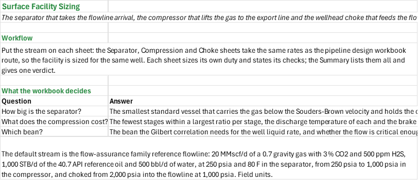
What does the facility for one well stream need: how big a separator, how many compressor stages and how much power, and which choke bean? You enter the stream's gas, oil and water rates, the gas composition, the separator, compressor and choke pressures and the design basis. You read off the recommended separator size and the rating of an existing vessel, the compressor stages, discharge temperature and brake power against the driver, and the bean with the rate it passes and whether the flow is critical.
How to use it: Put the stream on each sheet; the defaults are the same rates as the pipeline design workbook's route, so the facility is sized for the same well. On the Separator sheet enter the operating pressure and temperature, the orientation and phases, the retention times from bottle tests, the K factor from the mist extractor's rating, the slenderness limits and the existing vessel. On the Compression sheet enter the suction and discharge pressures, the machine basis and efficiencies, the largest ratio per stage, the temperature limit and the driver rating. On the Choke sheet enter the wellhead and flowline pressures and the well stream. Each sheet states its own checks; the Summary lists them all and gives one verdict.
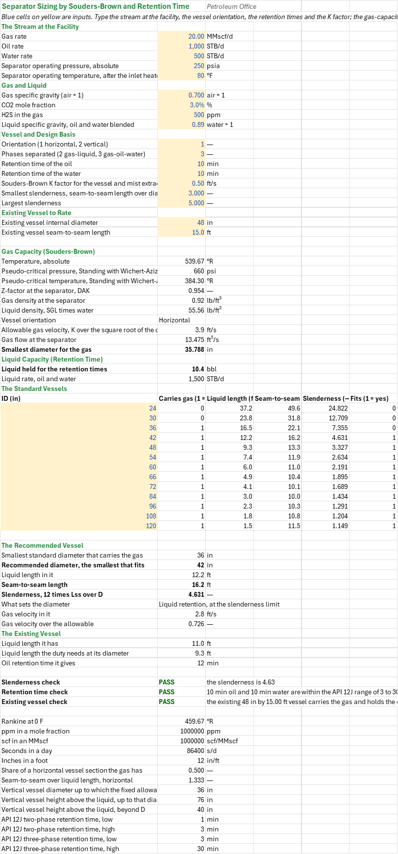
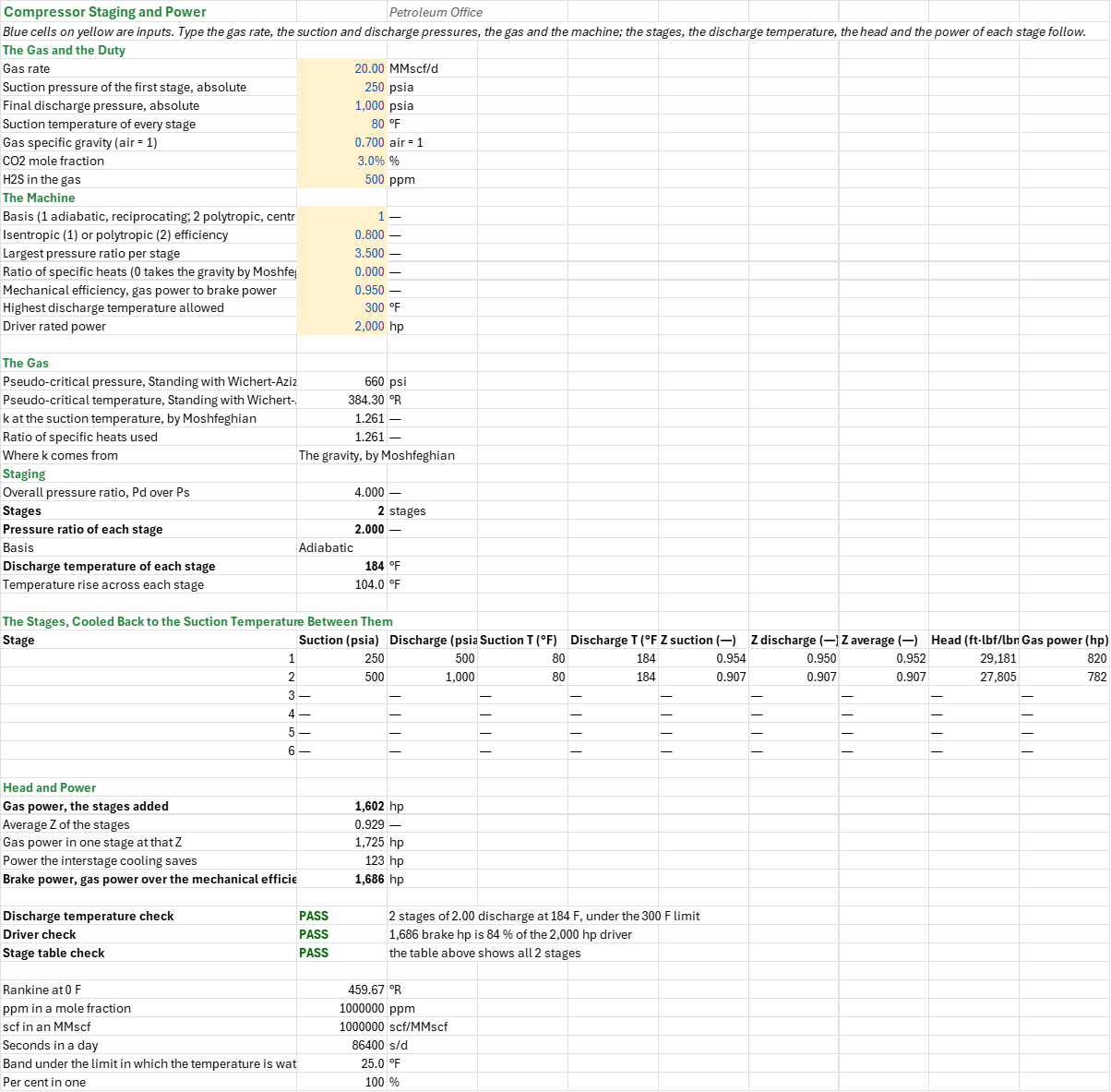
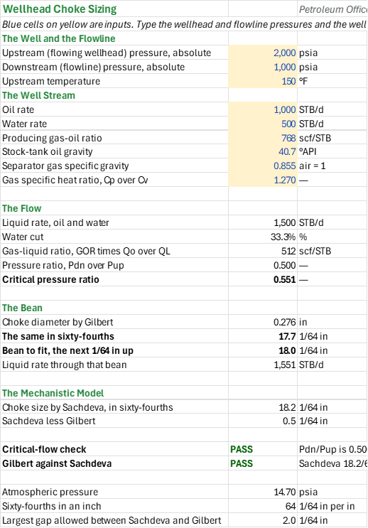
Method: The separator is sized by Souders-Brown for the gas and by the retention times for the liquid: the allowable gas velocity is K over the square root of the density ratio, with the gas density from a DAK Z-factor on Standing pseudo-criticals corrected for CO2 and H2S by Wichert-Aziz. The recommended vessel is the smallest standard diameter that carries the gas within the allowable velocity and holds the oil and water for their times within the slenderness limits (seam-to-seam length over diameter); the existing vessel is rated against the same duty. The compression takes the fewest stages within a largest ratio per stage, the discharge temperature of each stage cooled back to the suction temperature between stages, and the head and gas power of each stage at its own average Z, with k from the gas gravity by Moshfeghian unless a value is typed; the brake power is the gas power over the mechanical efficiency. The choke is sized by Gilbert's critical-flow correlation for the liquid rate and gas-liquid ratio, rounded up to the next 1/64 in, and checked against the critical pressure ratio from k, with Sachdeva's mechanistic model beside it as a second opinion.
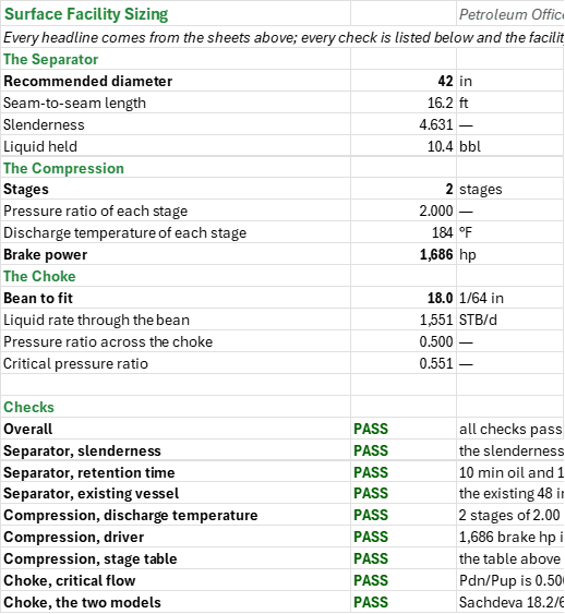
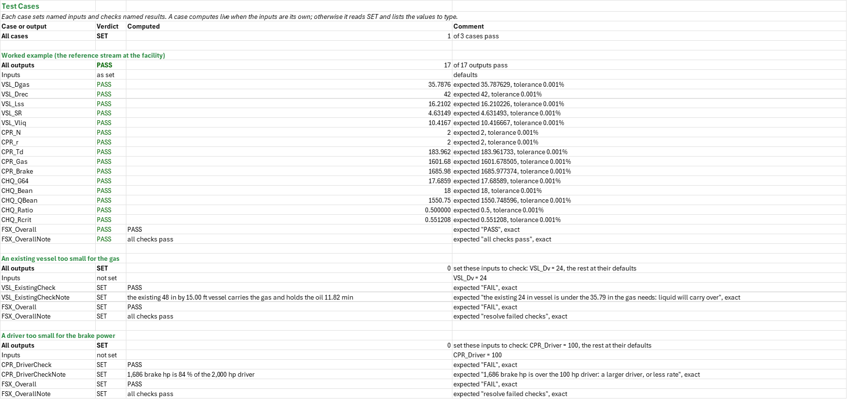
Example: The default stream is the flow-assurance family's reference flowline: 20 MMscf/d of a 0.7 gravity gas with 3 % CO2 and 500 ppm H2S, 1,000 STB/d of the 40.7 API reference oil and 500 bbl/d of water, at 250 psia and 80 F in the separator, compressed from 250 psia to 1,000 psia, and choked from 2,000 psia into the flowline at 1,000 psia. The separator needs 35.79 in for the gas, so the recommended vessel is 42 in by 16.21 ft seam to seam, a slenderness of 4.63. The compressor takes two stages at a ratio of 2, each discharging at 184 F, and needs 1,686 brake hp, 84 % of the 2,000 hp driver. The choke is 18/64 in, passing 1,551 bbl/d at a pressure ratio of 0.500, at or below the critical 0.551, so the flow is critical and Gilbert's correlation applies.
Validity
The Souders-Brown K factor has to come from the mist extractor's rating and the retention times from bottle tests: the sheet checks them against API 12J's ranges (1 to 3 min two-phase, 3 to 30 min three-phase) but cannot set them. The compression is steady and ignores real-gas deviation beyond the stages' own Z; a real machine needs its vendor's polytropic data. Gilbert's correlation applies only where the flow is critical, which the critical-flow check states.
References
- Souders, M. and Brown, G.G. (1934). Design of Fractionating Columns I. Entrainment and Capacity. Ind. Eng. Chem. 26(1), 98-103.
- Gilbert, W.E. (1954). Flowing and Gas-Lift Well Performance. API Drilling and Production Practice, 126-157 (the choke's critical-flow correlation).
- Sachdeva, R., Schmidt, Z., Brill, J.P. and Blais, R.M. (1986). Two-Phase Flow Through Chokes. SPE-15657-MS.
- API Spec 12J, Specification for Oil and Gas Separators.
- Arnold, K. and Stewart, M. (2008). Surface Production Operations, Vol. 1: Design of Oil Handling Systems and Facilities, 3rd ed. Gulf Professional Publishing.
- GPSA (2012). Engineering Data Book, 13th ed., section 17.
Inputs
| Input | Unit | Default | Name |
|---|---|---|---|
| Gas rate (Separator) | MMscf/d | 20 | VSL_Qg |
| Oil rate (Separator) | STB/d | 1,000 | VSL_Qo |
| Water rate (Separator) | bbl/d | 500 | VSL_Qw |
| Separator operating pressure, absolute | psia | 250 | VSL_P |
| Separator operating temperature, after the inlet heater | F | 80 | VSL_T |
| Gas specific gravity (air = 1) | — | 0.7 | VSL_SG |
| CO2 mole fraction | % | 3 | VSL_CO2 |
| H2S in the gas | ppm | 500 | VSL_H2S |
| Liquid specific gravity, oil and water blended | — | 0.89 | VSL_SGL |
| Orientation (1 horizontal, 2 vertical) | — | 1 | VSL_Orient |
| Phases separated (2 gas-liquid, 3 gas-oil-water) | — | 3 | VSL_Phases |
| Retention time of the oil | min | 10 | VSL_TrO |
| Retention time of the water | min | 10 | VSL_TrW |
| Souders-Brown K factor for the vessel and mist extractor | ft/s | 0.5 | VSL_K |
| Smallest slenderness, seam-to-seam length over diameter | — | 3 | VSL_SRmin |
| Largest slenderness | — | 5 | VSL_SRmax |
| Existing vessel internal diameter | in | 48 | VSL_Dv |
| Existing vessel seam-to-seam length | ft | 15 | VSL_Lv |
| Gas rate (Compression) | MMscf/d | 20 | CPR_Qg |
| Suction pressure of the first stage, absolute | psia | 250 | CPR_Ps |
| Final discharge pressure, absolute | psia | 1,000 | CPR_Pd |
| Suction temperature of every stage | F | 80 | CPR_Ts |
| Gas specific gravity (air = 1) | — | 0.7 | CPR_SG |
| CO2 mole fraction, H2S in the gas | %, ppm | 3, 500 | CPR_CO2, CPR_H2S |
| Basis (1 adiabatic, reciprocating; 2 polytropic, centrifugal) | — | 1 | CPR_Mode |
| Isentropic (1) or polytropic (2) efficiency | — | 0.8 | CPR_Eff |
| Largest pressure ratio per stage | — | 3.5 | CPR_Rmax |
| Ratio of specific heats (0 takes the gravity by Moshfeghian) | — | 0 | CPR_kTyped |
| Mechanical efficiency, gas power to brake power | — | 0.95 | CPR_Mech |
| Highest discharge temperature allowed | F | 300 | CPR_Tmax |
| Driver rated power | hp | 2,000 | CPR_Driver |
| Upstream (flowing wellhead) pressure, absolute | psia | 2,000 | CHQ_Pup |
| Downstream (flowline) pressure, absolute | psia | 1,000 | CHQ_Pdn |
| Upstream temperature | F | 150 | CHQ_T |
| Oil rate (Choke) | STB/d | 1,000 | CHQ_Qo |
| Water rate (Choke) | bbl/d | 500 | CHQ_Qw |
| Producing gas-oil ratio | scf/STB | 768 | CHQ_GOR |
| Stock-tank oil gravity | °API | 40.7 | CHQ_API |
| Separator gas specific gravity | — | 0.855 | CHQ_SGg |
| Gas specific heat ratio, Cp over Cv | — | 1.27 | CHQ_k |
Sheets
Guide— what the workbook decides (how big the separator, what the compression costs, which bean) and the default stream.Separator— the stream at the facility, gas and liquid densities, the Souders-Brown allowable velocity and the diameter the gas needs, the liquid held for the retention times, the standard vessels from 24 to 120 in with their lengths and slenderness, the recommended vessel and what sets its diameter, the existing vessel's rating, and the slenderness, retention-time and existing-vessel checks.Compression— the gas and the duty, k, the overall and per-stage ratios, the stages cooled back to the suction temperature between them, each stage's discharge temperature, Z and gas power, the power the interstage cooling saves, the brake power and the checks.Choke— the wellhead and flowline pressures and the well stream, the liquid rate, water cut, gas-liquid ratio and pressure ratio against the critical ratio, the Gilbert bean and the rate through it, and the Sachdeva size beside it.Summary— the separator, compression and choke headlines and every check under one verdict.Test Cases— the worked example and other cases, with expected and computed results.
Functions used
Names (164)
| Name | Refers to | Comment |
|---|---|---|
PO.SF.Comp.PowerLAMBDA |
=LAMBDA(mode, qg, ps, pd, t, sg, z, k, eff, stages, output, IF(OR(AND(mode<>"Adiabatic", mode<>"Polytropic"), qg<=0, ps<=0, pd<ps, t<=-459.67, sg<=0, z<=0, k<=1, eff<=0, eff>1, stages<1, stages<>INT(stages)), NA(), IF(OR(output="Head", output="Stage", output="Total"), z*1545.349*(t+459.67)/(28.9625*sg)/IF(mode="Polytropic", (k-1)/(k*eff), (k-1)/k)*(((pd/ps)^(1/stages))^IF(mode="Polytropic", (k-1)/(k*eff), (k-1)/k)-1)*IF(output="Head", 1, qg*1000000*14.696/(10.7316*519.67)*(28.9625*sg)/1440)/IF(output="Head", 1, eff*33000)*IF(output="Total", stages, 1), NA()))) |
Compressor gas power, "Adiabatic" or "Polytropic", equal-ratio stages intercooled to t: "Head" per stage (ft-lbf/lbm), "Stage" gas hp per stage or "Total" gas hp, for qg MMscf/d from ps to pd psia. |
PO.SF.Comp.StagesLAMBDA |
=LAMBDA(ps, pd, r_max, output, IF(OR(ps<=0, pd<=ps, r_max<=1), NA(), LET(n, MAX(1, ROUNDUP(LN(pd/ps)/LN(r_max)-0.000000001, 0)), IF(output="Stages", n, IF(output="Ratio", (pd/ps)^(1/n), NA()))))) |
Compression stages, equal ratios: "Stages" = fewest n with (pd/ps)^(1/n) <= r_max, or "Ratio" = (pd/ps)^(1/n) per stage, for suction ps and discharge pd (psia). |
PO.SF.Comp.TdischLAMBDA |
=LAMBDA(t, ratio, k, eff, IF(OR(t<=-459.67, ratio<1, k<=1, eff<=0, eff>1), NA(), (t+459.67)*(1+(ratio^((k-1)/k)-1)/eff)-459.67)) |
Adiabatic discharge temperature (deg F) of one stage: T1 + T1*(ratio^((k-1)/k) - 1)/eff, suction t (deg F), stage pressure ratio, k = Cp/Cv and isentropic efficiency eff (1 = ideal). |
PO.SF.Comp.kLAMBDA |
=LAMBDA(sg, t, IF(OR(sg<0.55, sg>2, t<-13, t>302), NA(), (1.6-0.44*sg+0.097*sg^2)*(1+0.0385*sg-0.000159*(t+459.67)))) |
Ideal-gas ratio of specific heats k = Cp/Cv of a hydrocarbon gas of gravity sg (0.55 to 2.0) at t (deg F, -13 to 302), Moshfeghian (2013) correlation; #N/A outside its range. |
PO.SF.Sep.LiquidRetentionLAMBDA |
=LAMBDA(phases, orientation, qo, qw, tr_o, tr_w, d, output, IF(OR(AND(phases<>2, phases<>3), AND(orientation<>"Vertical", orientation<>"Horizontal"), qo<0, qw<0, tr_o<0, tr_w<0, d<=0), NA(), IF(OR(output="Volume", output="Length"), IF(phases=2, (qo+qw)*tr_o, qo*tr_o+qw*tr_w)/1440*IF(output="Volume", 1, 5.6145833)/IF(output="Volume", 1, PI()/4*(d/12)^2*IF(orientation="Vertical", 1, 0.5)), NA()))) |
Separator liquid retention: "Volume" (bbl) to hold oil qo and water qw (bbl/d) for tr_o/tr_w (min), 2 or 3 phases, or "Length" (ft) of liquid at ID d (in), "Vertical" full section or "Horizontal" half full. |
PO.SF.Sep.SoudersBrownLAMBDA |
=LAMBDA(orientation, qg, p, t, z, sg, rho_l, k_sb, output, IF(OR(AND(orientation<>"Vertical", orientation<>"Horizontal"), qg<=0, p<=0, t<=-459.67, z<=0, sg<=0, k_sb<=0), NA(), LET(tabs, t+459.67, rho_g, 28.9625*sg*p/(10.7316*z*tabs), IF(rho_l<=rho_g, NA(), LET(vel, k_sb*SQRT(MAX(0, rho_l-rho_g)/rho_g), qa, qg*1000000*(14.696/p)*(tabs/519.67)*z/86400, frac, IF(orientation="Vertical", 1, 0.5), IF(output="Velocity", vel, IF(output="Diameter", 12*SQRT(4*qa/(MAX(vel, 0.000001)*frac)/PI()), NA()))))))) |
Souders-Brown separator gas capacity: "Velocity" allowable gas velocity (ft/s) = K*sqrt((rho_l-rho_g)/rho_g), or "Diameter" minimum vessel ID (in), "Vertical" or "Horizontal" (half full of liquid). |
CHQ_API |
Choke!$B$11 |
Stock-tank oil gravity, °API |
CHQ_Bean |
Choke!$B$25 |
Bean to fit, the next 1/64 in up, 1/64 in |
CHQ_Checks |
Choke!$B$32:$B$33 |
The critical-flow check and the Gilbert against Sachdeva check |
CHQ_CriticalCheck |
Choke!$B$32 |
Critical-flow check verdict |
CHQ_CriticalCheckNote |
Choke!$C$32 |
Critical-flow check comment |
CHQ_G |
Choke!$B$23 |
Choke diameter by Gilbert, in |
CHQ_G64 |
Choke!$B$24 |
The same in sixty-fourths, 1/64 in |
CHQ_GLR |
Choke!$B$18 |
Gas-liquid ratio, GOR times Qo over QL, scf/STB |
CHQ_GOR |
Choke!$B$10 |
Producing gas-oil ratio, scf/STB |
CHQ_Gap |
Choke!$B$30 |
Sachdeva less Gilbert, 1/64 in |
CHQ_Inputs |
Choke!$B$4:$B$13 |
The wellhead and flowline pressures, the upstream temperature, the oil and water rates, the gas-oil ratio, the oil gravity, the separator gas gravity and the specific heat ratio |
CHQ_ModelCheck |
Choke!$B$33 |
Gilbert against Sachdeva verdict |
CHQ_ModelCheckNote |
Choke!$C$33 |
Gilbert against Sachdeva comment |
CHQ_N64 |
Choke!$B$36 |
Sixty-fourths in an inch, 1/64 in per in |
CHQ_Patm |
Choke!$B$35 |
Atmospheric pressure, psia |
CHQ_Pdn |
Choke!$B$5 |
Downstream (flowline) pressure, absolute, psia |
CHQ_Pup |
Choke!$B$4 |
Upstream (flowing wellhead) pressure, absolute, psia |
CHQ_QBean |
Choke!$B$26 |
Liquid rate through that bean, STB/d |
CHQ_QL |
Choke!$B$16 |
Liquid rate, oil and water, STB/d |
CHQ_Qo |
Choke!$B$8 |
Oil rate, STB/d |
CHQ_Qw |
Choke!$B$9 |
Water rate, STB/d |
CHQ_Ratio |
Choke!$B$19 |
Pressure ratio, Pdn over Pup |
CHQ_Rcrit |
Choke!$B$20 |
Critical pressure ratio |
CHQ_Results |
Choke!$B$16:$B$30 |
The liquid rate, water cut, gas-liquid ratio and pressure ratio, the critical ratio, the bean and the rate through it, and the Sachdeva size |
CHQ_S64 |
Choke!$B$29 |
Choke size by Sachdeva, in sixty-fourths, 1/64 in |
CHQ_SGg |
Choke!$B$12 |
Separator gas specific gravity, air = 1 |
CHQ_T |
Choke!$B$6 |
Upstream temperature, °F |
CHQ_Tol |
Choke!$B$37 |
Largest gap allowed between Sachdeva and Gilbert, 1/64 in |
CHQ_WC |
Choke!$B$17 |
Water cut, % |
CHQ_k |
Choke!$B$13 |
Gas specific heat ratio, Cp over Cv |
CPR_Band |
Compression!$B$58 |
Band under the limit in which the temperature is watched, °F |
CPR_Basis |
Compression!$B$30 |
Basis |
CPR_Brake |
Compression!$B$48 |
Brake power, gas power over the mechanical efficiency, hp |
CPR_CO2 |
Compression!$B$9 |
CO2 mole fraction, % |
CPR_Checks |
Compression!$B$50:$B$52 |
The discharge temperature check, the driver check and the stage table check |
CPR_Driver |
Compression!$B$18 |
Driver rated power, hp |
CPR_DriverCheck |
Compression!$B$51 |
Driver check verdict |
CPR_DriverCheckNote |
Compression!$C$51 |
Driver check comment |
CPR_Eff |
Compression!$B$13 |
Isentropic (1) or polytropic (2) efficiency |
CPR_Gas |
Compression!$B$44 |
Gas power, the stages added, hp |
CPR_H2S |
Compression!$B$10 |
H2S in the gas, ppm |
CPR_Inputs |
Compression!$B$4:$B$18 |
The gas rate, the suction and final discharge pressures, the suction temperature, the gas gravity, CO2 and H2S, the basis, the efficiency, the largest ratio per stage, k, the mechanical efficiency, the discharge temperature limit and the driver rating |
CPR_Mech |
Compression!$B$16 |
Mechanical efficiency, gas power to brake power |
CPR_Mode |
Compression!$B$12 |
Basis (1 adiabatic, reciprocating; 2 polytropic, centrifugal) |
CPR_N |
Compression!$B$28 |
Stages, stages |
CPR_One |
Compression!$B$46 |
Gas power in one stage at that Z, hp |
CPR_Pct |
Compression!$B$59 |
Per cent in one, % |
CPR_Pd |
Compression!$B$6 |
Final discharge pressure, absolute, psia |
CPR_Ppc |
Compression!$B$21 |
Pseudo-critical pressure, Standing with Wichert-Aziz, psi |
CPR_Ppm |
Compression!$B$55 |
ppm in a mole fraction, ppm |
CPR_Ps |
Compression!$B$5 |
Suction pressure of the first stage, absolute, psia |
CPR_Qg |
Compression!$B$4 |
Gas rate, MMscf/d |
CPR_R0 |
Compression!$B$54 |
Rankine at 0 F, °R |
CPR_Rall |
Compression!$B$27 |
Overall pressure ratio, Pd over Ps |
CPR_Results |
Compression!$B$21:$B$48 |
The pseudo-criticals, k, the overall and per-stage ratios, the stages, the discharge temperature, the gas power by stage, the brake power and the three checks |
CPR_Rmax |
Compression!$B$14 |
Largest pressure ratio per stage |
CPR_SG |
Compression!$B$8 |
Gas specific gravity (air = 1), air = 1 |
CPR_Saved |
Compression!$B$47 |
Power the interstage cooling saves, hp |
CPR_Scf |
Compression!$B$56 |
scf in an MMscf, scf/MMscf |
CPR_Sec |
Compression!$B$57 |
Seconds in a day, s/d |
CPR_Stages |
Compression!$A$36:$J$41 |
Each stage: its suction and discharge pressures and temperatures, Z at each end and their average, its head and gas power |
CPR_StagesCheck |
Compression!$B$52 |
Stage table check verdict |
CPR_StagesCheckNote |
Compression!$C$52 |
Stage table check comment |
CPR_Td |
Compression!$B$31 |
Discharge temperature of each stage, °F |
CPR_TempCheck |
Compression!$B$50 |
Discharge temperature check verdict |
CPR_TempCheckNote |
Compression!$C$50 |
Discharge temperature check comment |
CPR_Tmax |
Compression!$B$17 |
Highest discharge temperature allowed, °F |
CPR_Tpc |
Compression!$B$22 |
Pseudo-critical temperature, Standing with Wichert-Aziz, °R |
CPR_Ts |
Compression!$B$7 |
Suction temperature of every stage, °F |
CPR_Zall |
Compression!$B$45 |
Average Z of the stages |
CPR_dT |
Compression!$B$32 |
Temperature rise across each stage, °F |
CPR_k |
Compression!$B$24 |
Ratio of specific heats used |
CPR_kCalc |
Compression!$B$23 |
k at the suction temperature, by Moshfeghian |
CPR_kFrom |
Compression!$B$25 |
Where k comes from |
CPR_kTyped |
Compression!$B$15 |
Ratio of specific heats (0 takes the gravity by Moshfeghian) |
CPR_r |
Compression!$B$29 |
Pressure ratio of each stage |
FSX_Bean |
Summary!$B$14 |
Bean to fit, 1/64 in |
FSX_Brake |
Summary!$B$12 |
Brake power, hp |
FSX_Checks |
Summary!$B$21:$B$28 |
Every check |
FSX_Drec |
Summary!$B$4 |
Recommended diameter, in |
FSX_Lss |
Summary!$B$5 |
Seam-to-seam length, ft |
FSX_Overall |
Summary!$B$20 |
Overall verdict |
FSX_OverallNote |
Summary!$C$20 |
Overall comment |
FSX_QBean |
Summary!$B$15 |
Liquid rate through the bean, STB/d |
FSX_Ratio |
Summary!$B$16 |
Pressure ratio across the choke |
FSX_Rcrit |
Summary!$B$17 |
Critical pressure ratio |
FSX_Results |
Summary!$B$4:$B$17 |
The separator, the compression and the choke |
FSX_SR |
Summary!$B$6 |
Slenderness |
FSX_Stages |
Summary!$B$9 |
Stages, stages |
FSX_Td |
Summary!$B$11 |
Discharge temperature of each stage, °F |
FSX_Verdict |
Summary!$B$20:$B$20 |
The overall verdict |
FSX_Vliq |
Summary!$B$7 |
Liquid held, bbl |
FSX_r |
Summary!$B$10 |
Pressure ratio of each stage |
VSL_CO2 |
Separator!$B$11 |
CO2 mole fraction, % |
VSL_Checks |
Separator!$B$70:$B$72 |
The slenderness check, the retention time check and the existing vessel check |
VSL_Dgas |
Separator!$B$36 |
Smallest diameter for the gas, in |
VSL_Drec |
Separator!$B$58 |
Recommended diameter, the smallest that fits, in |
VSL_Dstd |
Separator!$B$57 |
Smallest standard diameter that carries the gas, in |
VSL_Dv |
Separator!$B$23 |
Existing vessel internal diameter, in |
VSL_ExistingCheck |
Separator!$B$72 |
Existing vessel check verdict |
VSL_ExistingCheckNote |
Separator!$C$72 |
Existing vessel check comment |
VSL_Governs |
Separator!$B$62 |
What sets the diameter |
VSL_H2S |
Separator!$B$12 |
H2S in the gas, ppm |
VSL_Half |
Separator!$B$79 |
Share of a horizontal vessel section the gas has |
VSL_InFt |
Separator!$B$78 |
Inches in a foot, in/ft |
VSL_Inputs |
Separator!$B$4:$B$24 |
The stream at the facility, the vessel orientation, the retention times, the K factor and the slenderness limits, and the existing vessel size |
VSL_K |
Separator!$B$19 |
Souders-Brown K factor for the vessel and mist extractor, ft/s |
VSL_Leff |
Separator!$B$59 |
Liquid length in it, ft |
VSL_Lss |
Separator!$B$60 |
Seam-to-seam length, ft |
VSL_Lv |
Separator!$B$24 |
Existing vessel seam-to-seam length, ft |
VSL_LvLiq |
Separator!$B$66 |
Liquid length it has, ft |
VSL_LvNeed |
Separator!$B$67 |
Liquid length the duty needs at its diameter, ft |
VSL_Orient |
Separator!$B$15 |
Orientation (1 horizontal, 2 vertical) |
VSL_P |
Separator!$B$7 |
Separator operating pressure, absolute, psia |
VSL_Phases |
Separator!$B$16 |
Phases separated (2 gas-liquid, 3 gas-oil-water) |
VSL_Ppc |
Separator!$B$28 |
Pseudo-critical pressure, Standing with Wichert-Aziz, psi |
VSL_Ppm |
Separator!$B$75 |
ppm in a mole fraction, ppm |
VSL_QL |
Separator!$B$39 |
Liquid rate, oil and water, STB/d |
VSL_Qa |
Separator!$B$35 |
Gas flow at the separator, ft³/s |
VSL_Qg |
Separator!$B$4 |
Gas rate, MMscf/d |
VSL_Qo |
Separator!$B$5 |
Oil rate, STB/d |
VSL_Qw |
Separator!$B$6 |
Water rate, STB/d |
VSL_R0 |
Separator!$B$74 |
Rankine at 0 F, °R |
VSL_Results |
Separator!$B$27:$B$68 |
The gas and liquid densities, the Souders-Brown velocity and gas-capacity diameter, the liquid held, the recommended vessel and the existing vessel rating |
VSL_RetentionCheck |
Separator!$B$71 |
Retention time check verdict |
VSL_RetentionCheckNote |
Separator!$C$71 |
Retention time check comment |
VSL_RhoG |
Separator!$B$31 |
Gas density at the separator, lb/ft³ |
VSL_RhoL |
Separator!$B$32 |
Liquid density, SGL times water, lb/ft³ |
VSL_SG |
Separator!$B$10 |
Gas specific gravity (air = 1), air = 1 |
VSL_SGL |
Separator!$B$13 |
Liquid specific gravity, oil and water blended, water = 1 |
VSL_SR |
Separator!$B$61 |
Slenderness, 12 times Lss over D |
VSL_SRmax |
Separator!$B$21 |
Largest slenderness |
VSL_SRmin |
Separator!$B$20 |
Smallest slenderness, seam-to-seam length over diameter |
VSL_Scf |
Separator!$B$76 |
scf in an MMscf, scf/MMscf |
VSL_Sec |
Separator!$B$77 |
Seconds in a day, s/d |
VSL_Shell |
Separator!$B$80 |
Seam-to-seam over liquid length, horizontal |
VSL_SizeCheck |
Separator!$B$70 |
Slenderness check verdict |
VSL_SizeCheckNote |
Separator!$C$70 |
Slenderness check comment |
VSL_Sizes |
Separator!$A$42:$F$54 |
Each standard vessel diameter: whether it carries the gas, its liquid length for the retention times, its seam-to-seam length, its slenderness and whether it fits |
VSL_T |
Separator!$B$8 |
Separator operating temperature, after the inlet heater, °F |
VSL_TR |
Separator!$B$27 |
Temperature, absolute, °R |
VSL_Tpc |
Separator!$B$29 |
Pseudo-critical temperature, Standing with Wichert-Aziz, °R |
VSL_Tr2Hi |
Separator!$B$85 |
API 12J two-phase retention time, high, min |
VSL_Tr2Lo |
Separator!$B$84 |
API 12J two-phase retention time, low, min |
VSL_Tr3Hi |
Separator!$B$87 |
API 12J three-phase retention time, high, min |
VSL_Tr3Lo |
Separator!$B$86 |
API 12J three-phase retention time, low, min |
VSL_TrAvail |
Separator!$B$68 |
Oil retention time it gives, min |
VSL_TrO |
Separator!$B$17 |
Retention time of the oil, min |
VSL_TrW |
Separator!$B$18 |
Retention time of the water, min |
VSL_VertA |
Separator!$B$82 |
Vertical vessel height above the liquid, up to that diameter, in |
VSL_VertB |
Separator!$B$83 |
Vertical vessel height above the liquid, beyond D, in |
VSL_VertD |
Separator!$B$81 |
Vertical vessel diameter up to which the fixed allowance applies, in |
VSL_Vessel |
Separator!$B$33 |
Vessel orientation |
VSL_Vg |
Separator!$B$63 |
Gas velocity in it, ft/s |
VSL_VgRatio |
Separator!$B$64 |
Gas velocity over the allowable |
VSL_Vliq |
Separator!$B$38 |
Liquid held for the retention times, bbl |
VSL_Vt |
Separator!$B$34 |
Allowable gas velocity, K over the square root of the density ratio, ft/s |
VSL_Z |
Separator!$B$30 |
Z-factor at the separator, DAK |
Details
| Opens in | Needs the Petroleum Office add-in: its PO functions show #NAME? without it once Excel recalculates. Needs Microsoft 365 or Excel 2024: it uses functions Excel 2016 doesn't have, such as named LAMBDAs, which show #NAME? there. |
| File | FacilitySizing.xlsx, 37 KB |
| Category | Production |
| For agents and tools | Descriptor (.md) |