DST and Multi-rate Test Analysis
Description
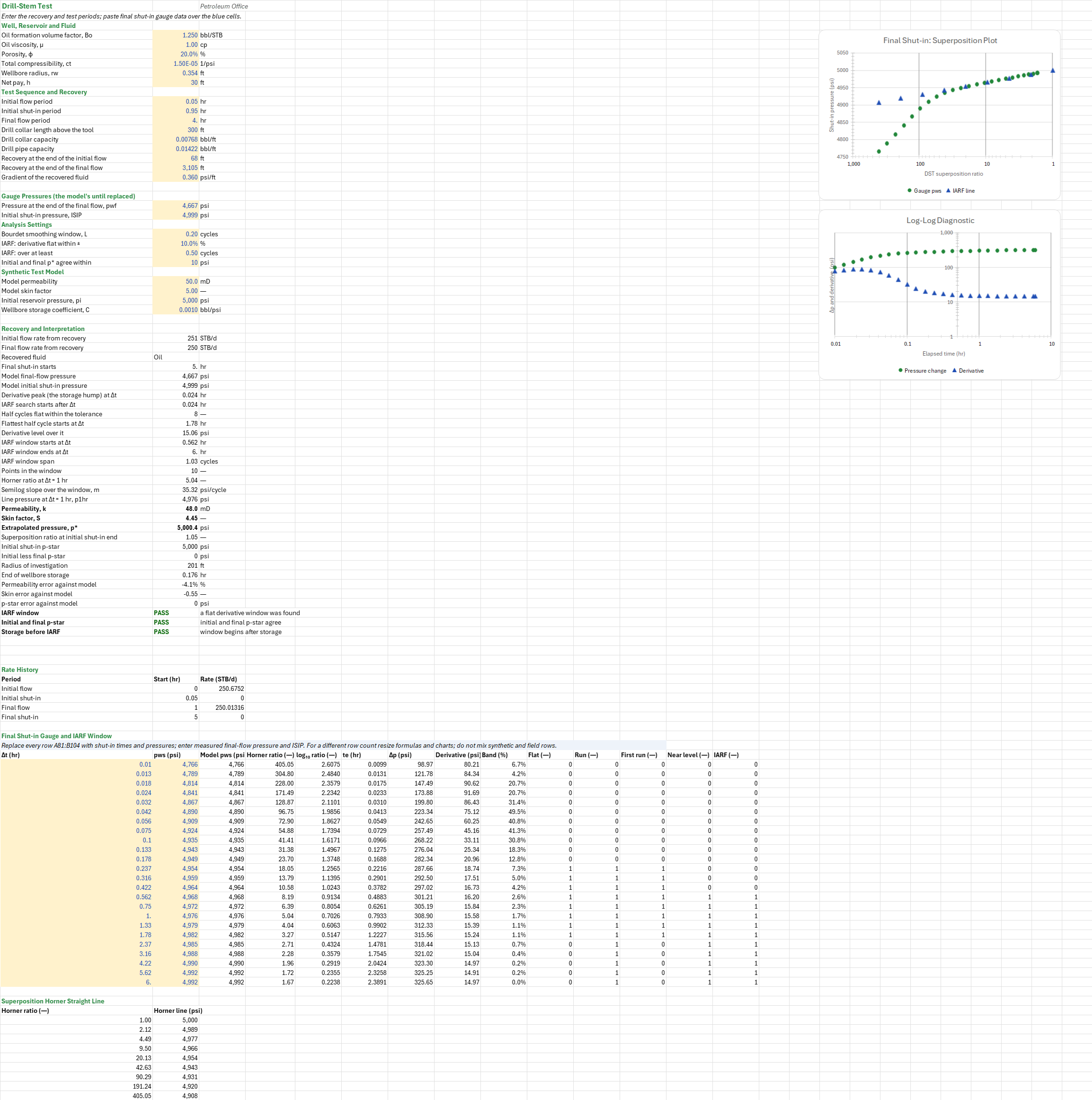
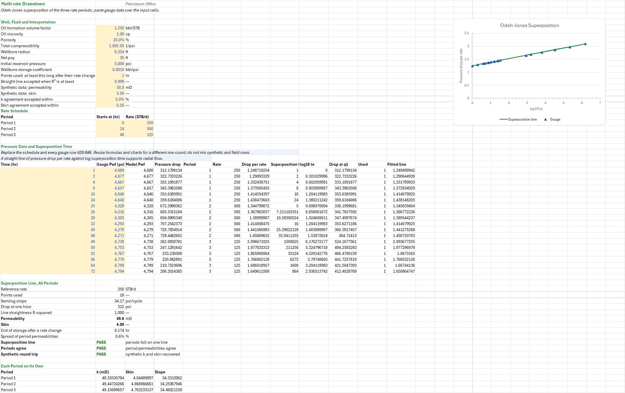
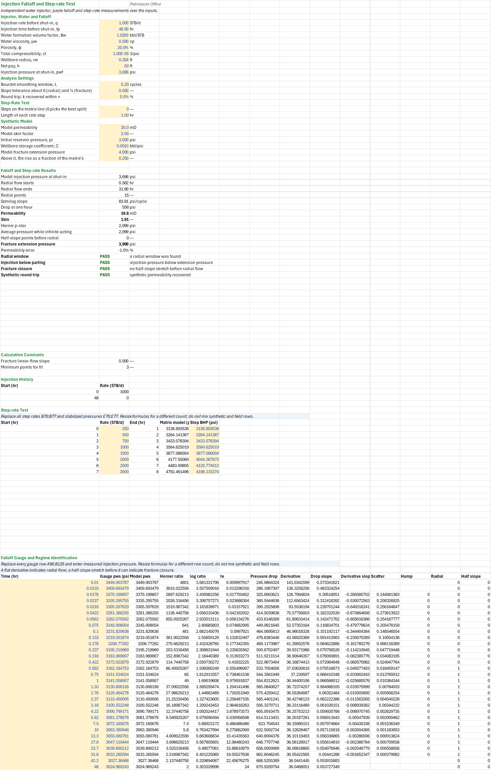
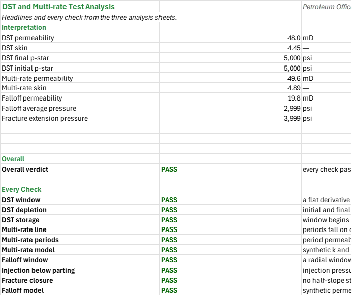
What permeability, skin and p-star do a drill-stem test, a variable-rate drawdown and a water-injection falloff give, and at what pressure does the injector fracture? You enter the DST periods and recovery, the drawdown's rate periods and the injector's rate and injection time, and paste each gauge record and the step rates. You read off the DST flow rates, k, skin and initial and final p-star; k and skin from one superposition line; and the injector's k, skin and fracture extension pressure. The defaults are synthetic gauge records, not field measurements.
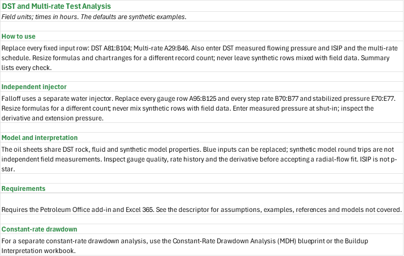
How to use it: The oil sheets use the shared rock and fluid inputs on the DST sheet; the Falloff sheet uses a separate water injector. On the DST sheet enter the durations and recovery, paste shut-in time and pressure over A81:B104, and type the measured final-flow pressure and ISIP over their model defaults. On the Multi-rate sheet enter the three rate periods and paste elapsed times and gauge pressures over A29:B46; check the sandface rates and exclude points affected by storage. On the Falloff sheet enter the injector's rate, injection duration and shut-in injection pressure, paste falloff times and pressures over A95:B125, and paste measured step rates and stabilized pressures over B70:B77 and E70:E77. Replace every fixed row before using field data; for a different record count resize all affected formulas and chart ranges, and never leave synthetic rows mixed with field measurements. Disregard every model-only check for real measurements. For a measured constant-rate drawdown use the drawdown analysis blueprint; the Buildup Interpretation workbook has only a model-only drawdown check. The Summary is last and lists every check.
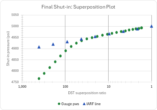
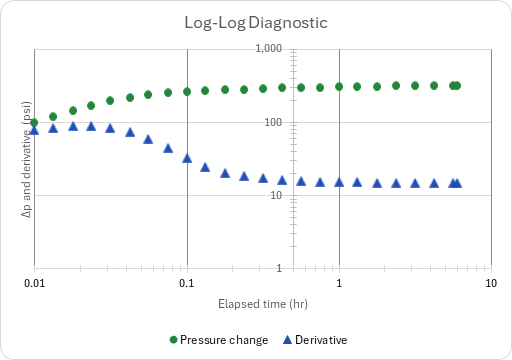
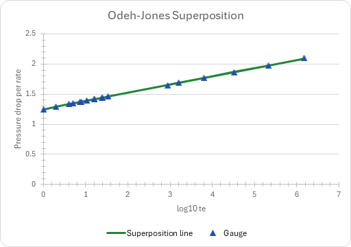
Method: Each analysis selects the radial-flow window from the Bourdet derivative and fits a straight line there, with permeability k = 162.6 q B mu/(m h) from the line's slope m. DST: the average flow rates come from the recovered column and the drill collar and pipe capacities over each flow period; the final shut-in is read on a superposition Horner plot, whose line gives permeability, skin and final p-star. The initial shut-in pressure (ISIP) is a gauge pressure, not p-star; it is extrapolated with the final line's slope, scaled to the initial flow rate, to compare initial and final p-star. Multi-rate: Odeh-Jones superposition maps the periods to one line of pressure drop per rate, delta p/qn, against log superposition time X = Σ (qj − qj−1)/qn log10(t − tj−1); all selected points and each period are fitted separately. Falloff: Agarwal equivalent time and the derivative identify the radial window, and a Miller-Dyes-Hutchinson line gives permeability and skin; a half-slope stretch can indicate fracture closure. The step-rate fit splits the stabilized pressures into a matrix line below the break and a second line above it, and the break gives the fracture extension pressure; the parting check fails above that pressure.
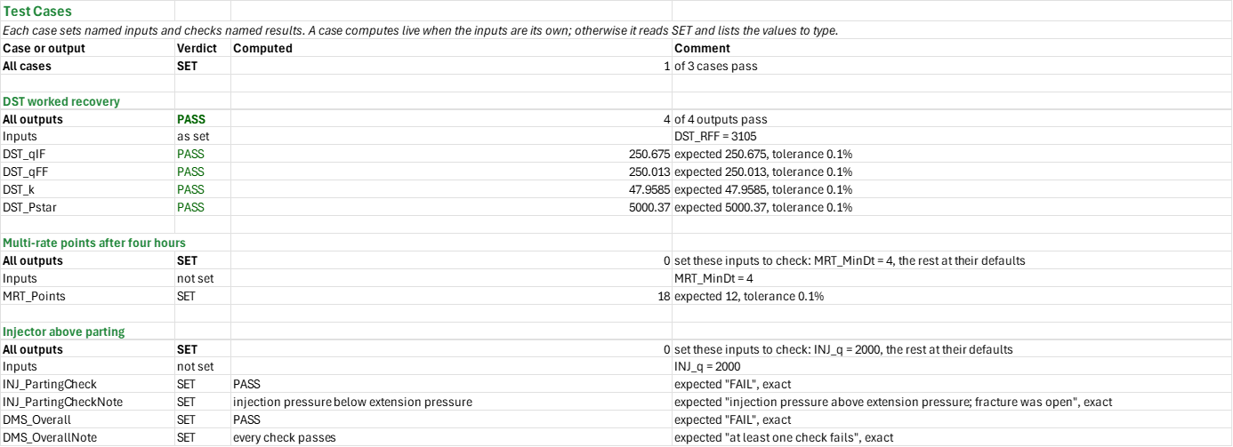
Example: With a DST final recovery of 3,105 ft, the final flow rate is 250.013 STB/d, the permeability 47.9585 mD and the final p-star 5,000.37 psi.
Validity
These straight-line methods assume a single-phase liquid, an infinite homogeneous reservoir and constant fluid properties, storage and skin. Rates must be representative of sandface conditions; DST recovery supplies period averages, not the transient flow rate. Inspect the derivative and the selected window: storage, boundaries, changing skin, multiphase flow and noisy gauges can bias the fit. The injector's p-star represents average pressure only while infinite-acting. A step-rate test needs stabilized pressures and sufficient steps on each side of the break; the synthetic knee is not a field measurement. An open fracture invalidates a simple radial falloff interpretation.
Named alternatives: nonlinear whole-record regression, a dual-porosity response, a fractured-injector falloff, the composite water-bank model, and the Matthews-Brons-Hazebroek bounded-pattern average-pressure correction, for which the add-in has no functions (the Engineering library has a mobility-bank injection test the add-in does not expose).
References
- Horner, D.R. (1951). Pressure Build-up in Wells. Proc. Third World Petroleum Congress, The Hague, Sec. II, 503-523.
- Miller, C.C., Dyes, A.B. and Hutchinson, C.A. (1950). The Estimation of Permeability and Reservoir Pressure from Bottom Hole Pressure Build-up Characteristics. Trans. AIME 189, 91-104.
- Matthews, C.S., Brons, F. and Hazebroek, P. (1954). A Method for Determination of Average Pressure in a Bounded Reservoir. Trans. AIME 201, 182-191.
- Odeh, A.S. and Jones, L.G. (1965). Pressure Drawdown Analysis, Variable-Rate Case. JPT 17(8), 960-964.
- Earlougher, R.C. (1977). Advances in Well Test Analysis. SPE Monograph 5.
- Agarwal, R.G. (1980). A New Method to Account for Producing Time Effects When Drawdown Type Curves Are Used to Analyze Pressure Buildup and Other Test Data. SPE-9289-MS.
- Bourdet, D., Ayoub, J.A. and Pirard, Y.M. (1989). Use of Pressure Derivative in Well-Test Interpretation. SPE Formation Evaluation 4(2), 293-302. SPE-12777-PA.
Inputs
One table for the three sheets: the DST sheet (DST_, its rock and fluid shared by the Multi-rate sheet), the Multi-rate sheet (MRT_; its rate schedule defaults to 250, 500 and 125 STB/d starting at 0, 24 and 48 hr) and the Falloff sheet (INJ_, a separate water injector).
| Input | Unit | Default | Name |
|---|---|---|---|
| Oil formation volume factor, Bo | bbl/STB | 1.25 | DST_Bo |
| Oil viscosity, μ | cp | 1 | DST_mu |
| Porosity, φ | fraction | 0.2 | DST_phi |
| Total compressibility, ct | 1/psi | 1.5E-05 | DST_ct |
| Wellbore radius, rw | ft | 0.354 | DST_rw |
| Net pay, h | ft | 30 | DST_h |
| Initial flow period | hr | 0.05 | DST_tIF |
| Initial shut-in period | hr | 0.95 | DST_tISI |
| Final flow period | hr | 4 | DST_tFF |
| Drill collar length above the tool | ft | 300 | DST_Lc |
| Drill collar capacity | bbl/ft | 0.00768 | DST_Cc |
| Drill pipe capacity | bbl/ft | 0.01422 | DST_Cp |
| Recovery at the end of the initial flow | ft | 68 | DST_RIF |
| Recovery at the end of the final flow | ft | 3105 | DST_RFF |
| Gradient of the recovered fluid | psi/ft | 0.36 | DST_Grad |
| Pressure at the end of the final flow, pwf | psi | model | DST_Pwf |
| Initial shut-in pressure, ISIP | psi | model | DST_ISIP |
| Bourdet smoothing window, L | cycles | 0.2 | DST_L |
| IARF: derivative flat within ± | fraction | 0.1 | DST_Flat |
| IARF: over at least | cycles | 0.5 | DST_Span |
| Initial and final p* agree within | psi | 10 | DST_PTol |
| Model permeability | mD | 50 | DST_ModelK |
| Model skin factor | — | 5 | DST_ModelS |
| Initial reservoir pressure, pi | psi | 5000 | DST_Pi |
| Wellbore storage coefficient, C | bbl/psi | 0.001 | DST_C |
| Points used: at least this long after their rate change | hr | 1 | MRT_MinDt |
| Straight line accepted when R² is at least | — | 0.999 | MRT_RsqMin |
| Synthetic data: permeability | mD | 50 | MRT_KSyn |
| Synthetic data: skin | — | 5 | MRT_SSyn |
| k agreement accepted within | fraction | 0.05 | MRT_KTol |
| Skin agreement accepted within | — | 0.5 | MRT_STol |
| Injection rate before shut-in, q | STB/d | 1000 | INJ_q |
| Injection time before shut-in, tp | hr | 48 | INJ_tp |
| Water formation volume factor, Bw | bbl/STB | 1.02 | INJ_Bw |
| Water viscosity, μw | cp | 0.5 | INJ_mu |
| Porosity, φ | fraction | 0.2 | INJ_phi |
| Total compressibility, ct | 1/psi | 1E-05 | INJ_ct |
| Wellbore radius, rw | ft | 0.354 | INJ_rw |
| Net pay, h | ft | 50 | INJ_h |
| Injection pressure at shut-in, pwf | psi | model | INJ_Pwf |
| Bourdet smoothing window, L | cycles | 0.2 | INJ_L |
| Slope tolerance about 0 (radial) and ½ (fracture) | — | 0.05 | INJ_Tol |
| Round trip: k recovered within ± | fraction | 0.05 | INJ_KTol |
| Steps on the matrix line (0 picks the best split) | — | 0 | INJ_nlow |
| Length of each rate step | hr | 1 | INJ_StepHr |
| Model permeability | mD | 20 | INJ_ModelK |
| Model skin factor | — | 2 | INJ_ModelS |
| Initial reservoir pressure, pi | psi | 3000 | INJ_Pi |
| Wellbore storage coefficient, C | bbl/psi | 0.001 | INJ_C |
| Model fracture extension pressure | psi | 4000 | INJ_ModelPfe |
| Above it, the rise as a fraction of the matrix's | — | 0.25 | INJ_Frac |
Sheets
Guide— how to replace the fixed input rows, the independent injector, model against interpretation, and where a constant-rate drawdown goes.DST— the shared rock and fluid, the test sequence and recovery, the flow rates from recovery, the four-period rate history, the final shut-in gauge with its Bourdet derivative and IARF window, the superposition Horner line with permeability, skin and final p-star, and the initial shut-in p-star against it.Multi-rate— the three-period rate schedule, the gauge pressures and superposition time, the Odeh-Jones line of pressure drop per rate against log superposition time fitted over all points and per period, and its chart.Falloff— the separate water injector: the falloff gauge on Agarwal equivalent time with its derivative, the MDH line with permeability, skin and p-star, and the step-rate test with the fracture extension pressure.Summary— the headlines and every check from the three analysis sheets.Test Cases— the worked example and other cases, with expected and computed results.
Functions used
Names (170)
| Name | Refers to | Comment |
|---|---|---|
PO.PTA.DST.SuperpositionLAMBDA |
=LAMBDA(t, rate_history, LET(ts, INDEX(rate_history, 0, 1), q, INDEX(rate_history, 0, 2), i, SEQUENCE(ROWS(ts)), active, --(ts<t), q_prev, MMULT(--(i=TRANSPOSE(i)+1), q), q_ref, INDEX(q, MAX(active*(q<>0)*i)), q_now, INDEX(q, MAX(active*i)), x, SUM(active*(q-q_prev)*LOG10(active*(t-ts)+(1-active)))/q_ref, IF(q_now<>0, NA(), 10^x))) |
Superposition Horner ratio of a shut-in after one or more flow periods (a DST's ISI or FSI): 10^Σ(Δq/q)·log10(t − t_start), the multi-rate (tp + Δt)/Δt, [dimensionless]. |
PO.PTA.Design.DurationLAMBDA |
=LAMBDA(C, mu, k, h, S, cycles, IF((200000+12000*S)*C*mu/(k*h)<=0, NA(), (200000+12000*S)*C*mu/(k*h)*10^cycles)) |
Test duration: the start of the semilog straight line, (200000 + 12000·S)·C·μ/(k·h), carried cycles log cycles further; cycles = 0 gives the start of the line itself, [h]. |
PO.PTA.Design.RinvLAMBDA |
=LAMBDA(k, t, phi, mu, ct, SQRT(k*t/(948*phi*mu*ct))) |
Radius of investigation of radial flow after t hours: sqrt(k·t / (948·φ·μ·ct)), [ft]. |
PO.PTA.Fluid.FromRecoveryLAMBDA |
=LAMBDA(Recovery_ft, Collar_ft, Collar_bblft, Pipe_bblft, Flow_h, Gradient_psift, LET(v, MIN(Recovery_ft, Collar_ft)*Collar_bblft+MAX(Recovery_ft-Collar_ft, 0)*Pipe_bblft, HSTACK(24*v/Flow_h, IF(Gradient_psift<0.4, 1, IF(Gradient_psift<=0.47, 2, 3))))) |
DST recovery to a fluid call, 1 oil, 2 water or 3 mud from its gradient, and an average flow rate: the column recovered in the collars and pipe over the flow time, [bbl/d]. |
PO.PTA.MDH.FitLAMBDA |
=LAMBDA(t, dp, q, B, mu, h, phi, ct, rw, output, LET(x, LOG10(t), m, SLOPE(dp, x), dp_1h, INTERCEPT(dp, x), perm, 162.6*q*B*mu/(m*h), skin, 1.151*(dp_1h/m-LOG10(perm/(phi*mu*ct*rw^2))+3.23), IF(m<=0, NA(), IF(output="k", perm, IF(output="S", skin, IF(output="m", m, IF(output="dp1h", dp_1h, NA()))))))) |
MDH semilog straight-line fit of a drawdown: least squares of Δp against log10(t) over the points given; output "k" [mD], "S" [dimensionless], "m" [psi/cycle] or "dp1h" [psi], the line's Δp at 1 h. |
PO.PTA.StepRate.FitLAMBDA |
=LAMBDA(q, p, nlow, output, LET(cnt, ROWS(q), qa, AVERAGE(q), pa, AVERAGE(p), qc, q-qa, pc, p-pa, ix, SEQUENCE(cnt), kk, SEQUENCE(cnt-3, 1, 2), msk, --(TRANSPOSE(ix)<=kk), nlo, kk, nhi, cnt-kk, sxlo, MMULT(msk, qc), sylo, MMULT(msk, pc), sxxlo, MMULT(msk, qc^2), sxylo, MMULT(msk, qc*pc), syylo, MMULT(msk, pc^2), sxhi, SUM(qc)-sxlo, syhi, SUM(pc)-sylo, sxxhi, SUM(qc^2)-sxxlo, sxyhi, SUM(qc*pc)-sxylo, syyhi, SUM(pc^2)-syylo, cxxlo, sxxlo-sxlo^2/nlo, cxylo, sxylo-sxlo*sylo/nlo, cxxhi, sxxhi-sxhi^2/nhi, cxyhi, sxyhi-sxhi*syhi/nhi, sse, syylo-sylo^2/nlo-cxylo^2/cxxlo+syyhi-syhi^2/nhi-cxyhi^2/cxxhi, pick, IF(nlow>0, nlow, MIN(IF(sse=MIN(sse), kk, cnt))), sel, --(kk=pick), slo, SUM(sel*cxylo/cxxlo), shi, SUM(sel*cxyhi/cxxhi), ilo, SUM(sel*(sylo-slo*sxlo)/nlo), ihi, SUM(sel*(syhi-shi*sxhi)/nhi), qx, IF(slo>shi, (ihi-ilo)/(slo-shi), 0), IF(OR(cnt<5, nlow<0, nlow=1, nlow>cnt-2, slo<=shi), NA(), IF(output="p", pa+ilo+slo*qx, IF(output="q", qa+qx, IF(output="mlo", slo, IF(output="mhi", shi, IF(output="n", pick, NA())))))))) |
Two-line step-rate test fit: least squares of the matrix and the fracture lines, split at nlow points (0 picks the split of least total squared error); output "p" extension pressure, "q" extension rate, "mlo", "mhi" slopes or "n" split. |
PO.PTA.Superposition.TimeLAMBDA |
=LAMBDA(t, prod_data, output, LET(ts, INDEX(prod_data, 0, 1), q, INDEX(prod_data, 0, 2), i, SEQUENCE(ROWS(ts)), active, --(ts<t), n, SUM(active), q_prev, MMULT(--(i=TRANSPOSE(i)+1), q), q_now, IF(n=0, 0, INDEX(q, MAX(active*i))), x, IF(q_now=0, 0, SUM(active*(q-q_prev)*LOG10(active*(t-ts)+(1-active)))/q_now), IF(q_now=0, NA(), IF(output="X", x, IF(output="te", 10^x, NA()))))) |
Odeh-Jones superposition time of a variable-rate drawdown: te = 10^X with X = Σ (qj − qj−1)/qn · log10(t − tj−1); output "te" returns te [h], "X" returns X [dimensionless]. #N/A when the active rate is 0. |
_PO.PTA.EndWBSLAMBDA |
=LAMBDA(C,mu,k,h,S, (200000+12000*S)*C*mu/(k*h)) |
End of wellbore storage time, h |
DMS_Checks |
Summary!$B$20:$B$29 |
Every named analysis check |
DMS_DstK |
Summary!$B$4 |
DST permeability, mD |
DMS_DstPstar |
Summary!$B$6 |
DST final p-star, psi |
DMS_DstPstarISI |
Summary!$B$7 |
DST initial p-star, psi |
DMS_DstS |
Summary!$B$5 |
DST skin |
DMS_FalloffK |
Summary!$B$10 |
Falloff permeability, mD |
DMS_FalloffPavg |
Summary!$B$11 |
Falloff average pressure, psi |
DMS_MultirateK |
Summary!$B$8 |
Multi-rate permeability, mD |
DMS_MultirateSkin |
Summary!$B$9 |
Multi-rate skin |
DMS_Overall |
Summary!$B$17 |
Overall verdict verdict |
DMS_OverallNote |
Summary!$C$17 |
Overall verdict comment |
DMS_Pfe |
Summary!$B$12 |
Fracture extension pressure, psi |
DMS_Results |
Summary!$B$4:$B$17 |
Headline interpretations and overall verdict |
DST_Analysis |
DST!$C$81:$N$104 |
Per row: the model pws, the Horner ratio, te, Δp, the Bourdet derivative, and the IARF window search |
DST_Bo |
DST!$B$4 |
Oil formation volume factor, Bo, bbl/STB |
DST_C |
DST!$B$33 |
Wellbore storage coefficient, C, bbl/psi |
DST_Cc |
DST!$B$15 |
Drill collar capacity, bbl/ft |
DST_CoreT |
DST!$B$45 |
Flattest half cycle starts at Δt, hr |
DST_Cp |
DST!$B$16 |
Drill pipe capacity, bbl/ft |
DST_Curve |
DST!$B$81:$D$104 |
Final Shut-in: Superposition Plot |
DST_Data |
DST!$A$81:$B$104 |
The shut-in data: Δt since shut-in and the shut-in pressure (the synthetic model's until you paste a gauge's) |
DST_DepletionCheck |
DST!$B$66 |
Initial and final p-star verdict |
DST_DepletionCheckNote |
DST!$C$66 |
Initial and final p-star comment |
DST_EndWBS |
DST!$B$61 |
End of wellbore storage, hr |
DST_Flat |
DST!$B$26 |
IARF: derivative flat within ±, % |
DST_Fluid |
DST!$B$38 |
Recovered fluid |
DST_From |
DST!$B$43 |
IARF search starts after Δt, hr |
DST_Grad |
DST!$B$19 |
Gradient of the recovered fluid, psi/ft |
DST_ISIP |
DST!$B$23 |
Initial shut-in pressure, ISIP, psi |
DST_ISIPModel |
DST!$B$41 |
Model initial shut-in pressure, psi |
DST_Inputs |
DST!$B$4:$B$33 |
Rock and fluid, the test sequence, the string and its recovery, the gauge pressures, the window settings and the synthetic model |
DST_L |
DST!$B$25 |
Bourdet smoothing window, L, cycles |
DST_Lc |
DST!$B$14 |
Drill collar length above the tool, ft |
DST_Level |
DST!$B$46 |
Derivative level over it, psi |
DST_ModelK |
DST!$B$30 |
Model permeability, mD |
DST_ModelS |
DST!$B$31 |
Model skin factor |
DST_P1hr |
DST!$B$53 |
Line pressure at Δt = 1 hr, p1hr, psi |
DST_PErr |
DST!$B$64 |
p-star error against model, psi |
DST_PTol |
DST!$B$28 |
Initial and final p* agree within, psi |
DST_Peak |
DST!$B$42 |
Derivative peak (the storage hump) at Δt, hr |
DST_Pi |
DST!$B$32 |
Initial reservoir pressure, pi, psi |
DST_Pstar |
DST!$B$56 |
Extrapolated pressure, p*, psi |
DST_PstarISI |
DST!$B$58 |
Initial shut-in p-star, psi |
DST_Pwf |
DST!$B$22 |
Pressure at the end of the final flow, pwf, psi |
DST_PwfModel |
DST!$B$40 |
Model final-flow pressure, psi |
DST_Qual |
DST!$B$44 |
Half cycles flat within the tolerance |
DST_R1hr |
DST!$B$51 |
Horner ratio at Δt = 1 hr |
DST_RFF |
DST!$B$18 |
Recovery at the end of the final flow, ft |
DST_RIF |
DST!$B$17 |
Recovery at the end of the initial flow, ft |
DST_RISI |
DST!$B$57 |
Superposition ratio at initial shut-in end |
DST_Rates |
DST!$A$73:$C$76 |
The four flow and shut-in periods |
DST_Results |
DST!$B$36:$B$67 |
DST recovery, interpretation and checks |
DST_Rinv |
DST!$B$60 |
Radius of investigation, ft |
DST_S |
DST!$B$55 |
Skin factor, S |
DST_SErr |
DST!$B$63 |
Skin error against model |
DST_Span |
DST!$B$27 |
IARF: over at least, cycles |
DST_StorageCheck |
DST!$B$67 |
Storage before IARF verdict |
DST_StorageCheckNote |
DST!$C$67 |
Storage before IARF comment |
DST_WinEnd |
DST!$B$48 |
IARF window ends at Δt, hr |
DST_WinN |
DST!$B$50 |
Points in the window |
DST_WinSpan |
DST!$B$49 |
IARF window span, cycles |
DST_WinStart |
DST!$B$47 |
IARF window starts at Δt, hr |
DST_WindowCheck |
DST!$B$65 |
IARF window verdict |
DST_WindowCheckNote |
DST!$C$65 |
IARF window comment |
DST_ct |
DST!$B$7 |
Total compressibility, ct, 1/psi |
DST_dPstar |
DST!$B$59 |
Initial less final p-star, psi |
DST_h |
DST!$B$9 |
Net pay, h, ft |
DST_k |
DST!$B$54 |
Permeability, k, mD |
DST_kErr |
DST!$B$62 |
Permeability error against model, % |
DST_m |
DST!$B$52 |
Semilog slope over the window, m, psi/cycle |
DST_mu |
DST!$B$5 |
Oil viscosity, μ, cp |
DST_phi |
DST!$B$6 |
Porosity, φ, % |
DST_qFF |
DST!$B$37 |
Final flow rate from recovery, STB/d |
DST_qIF |
DST!$B$36 |
Initial flow rate from recovery, STB/d |
DST_rw |
DST!$B$8 |
Wellbore radius, rw, ft |
DST_tFF |
DST!$B$13 |
Final flow period, hr |
DST_tIF |
DST!$B$11 |
Initial flow period, hr |
DST_tISI |
DST!$B$12 |
Initial shut-in period, hr |
DST_tShut |
DST!$B$39 |
Final shut-in starts, hr |
INJ_Bw |
Falloff!$B$6 |
Water formation volume factor, Bw, bbl/STB |
INJ_C |
Falloff!$B$24 |
Wellbore storage coefficient, C, bbl/psi |
INJ_ClosureCheck |
Falloff!$B$44 |
Fracture closure verdict |
INJ_ClosureCheckNote |
Falloff!$C$44 |
Fracture closure comment |
INJ_Data |
Falloff!$A$95:$B$125 |
Falloff time and pressure |
INJ_Dp1h |
Falloff!$B$34 |
Drop at one hour, psi |
INJ_Frac |
Falloff!$B$26 |
Above it, the rise as a fraction of the matrix's |
INJ_Half |
Falloff!$B$59 |
Fracture linear-flow slope |
INJ_Inputs |
Falloff!$B$4:$B$26 |
Rate, injection time, water and rock, the pressure at shut-in, the window settings, the step-rate split and step length, and the synthetic model |
INJ_K |
Falloff!$B$35 |
Permeability, mD |
INJ_KErr |
Falloff!$B$41 |
Permeability error, % |
INJ_KTol |
Falloff!$B$16 |
Round trip: k recovered within ±, % |
INJ_L |
Falloff!$B$14 |
Bourdet smoothing window, L, cycles |
INJ_M |
Falloff!$B$33 |
Semilog slope, psi/cycle |
INJ_MinN |
Falloff!$B$60 |
Minimum points for fit |
INJ_ModelK |
Falloff!$B$21 |
Model permeability, mD |
INJ_ModelPfe |
Falloff!$B$25 |
Model fracture extension pressure, psi |
INJ_ModelS |
Falloff!$B$22 |
Model skin factor |
INJ_NHalf |
Falloff!$B$39 |
Half-slope points before radial |
INJ_NRad |
Falloff!$B$32 |
Radial points |
INJ_PartingCheck |
Falloff!$B$43 |
Injection below parting verdict |
INJ_PartingCheckNote |
Falloff!$C$43 |
Injection below parting comment |
INJ_Pavg |
Falloff!$B$38 |
Average pressure while infinite-acting, psi |
INJ_Pfe |
Falloff!$B$40 |
Fracture extension pressure, psi |
INJ_Pi |
Falloff!$B$23 |
Initial reservoir pressure, pi, psi |
INJ_Pstar |
Falloff!$B$37 |
Horner p-star, psi |
INJ_Pwf |
Falloff!$B$12 |
Injection pressure at shut-in, pwf, psi |
INJ_PwfModel |
Falloff!$B$29 |
Model injection pressure at shut-in, psi |
INJ_RadEnd |
Falloff!$B$31 |
Radial flow ends, hr |
INJ_RadStart |
Falloff!$B$30 |
Radial flow starts, hr |
INJ_Rates |
Falloff!$A$64:$B$65 |
Injection then shut-in |
INJ_Results |
Falloff!$B$29:$B$45 |
Falloff results and checks |
INJ_S |
Falloff!$B$36 |
Skin |
INJ_StepHr |
Falloff!$B$19 |
Length of each rate step, hr |
INJ_Steps |
Falloff!$A$70:$B$77 |
Step starts and rates |
INJ_Tol |
Falloff!$B$15 |
Slope tolerance about 0 (radial) and ½ (fracture) |
INJ_TripCheck |
Falloff!$B$45 |
Synthetic round trip verdict |
INJ_TripCheckNote |
Falloff!$C$45 |
Synthetic round trip comment |
INJ_WindowCheck |
Falloff!$B$42 |
Radial window verdict |
INJ_WindowCheckNote |
Falloff!$C$42 |
Radial window comment |
INJ_ct |
Falloff!$B$9 |
Total compressibility, ct, 1/psi |
INJ_h |
Falloff!$B$11 |
Net pay, h, ft |
INJ_mu |
Falloff!$B$7 |
Water viscosity, μw, cp |
INJ_nlow |
Falloff!$B$18 |
Steps on the matrix line (0 picks the best split) |
INJ_phi |
Falloff!$B$8 |
Porosity, φ, % |
INJ_q |
Falloff!$B$4 |
Injection rate before shut-in, q, STB/d |
INJ_rw |
Falloff!$B$10 |
Wellbore radius, rw, ft |
INJ_tp |
Falloff!$B$5 |
Injection time before shut-in, tp, hr |
MRT_Bo |
'Multi-rate'!$B$5 |
Oil formation volume factor, bbl/STB |
MRT_C |
'Multi-rate'!$B$12 |
Wellbore storage coefficient, bbl/psi |
MRT_Ct |
'Multi-rate'!$B$8 |
Total compressibility, 1/psi |
MRT_Curve |
'Multi-rate'!$G$29:$L$46 |
Odeh-Jones Superposition |
MRT_Data |
'Multi-rate'!$A$29:$B$46 |
Elapsed time and gauge pressure |
MRT_Dp1h |
'Multi-rate'!$B$52 |
Drop at one hour, psi |
MRT_Inputs |
'Multi-rate'!$B$5:$B$18 |
Fluid and rock, the point selection and line tolerances, and the synthetic well's k and skin |
MRT_K |
'Multi-rate'!$B$54 |
Permeability, mD |
MRT_KSpread |
'Multi-rate'!$B$57 |
Spread of period permeabilities, % |
MRT_KSyn |
'Multi-rate'!$B$15 |
Synthetic data: permeability, mD |
MRT_KTol |
'Multi-rate'!$B$17 |
k agreement accepted within, % |
MRT_LineCheck |
'Multi-rate'!$B$58 |
Superposition line verdict |
MRT_LineCheckNote |
'Multi-rate'!$C$58 |
Superposition line comment |
MRT_M |
'Multi-rate'!$B$51 |
Semilog slope, psi/cycle |
MRT_MinDt |
'Multi-rate'!$B$13 |
Points used: at least this long after their rate change, hr |
MRT_ModelCheck |
'Multi-rate'!$B$60 |
Synthetic round trip verdict |
MRT_ModelCheckNote |
'Multi-rate'!$C$60 |
Synthetic round trip comment |
MRT_Mu |
'Multi-rate'!$B$6 |
Oil viscosity, cp |
MRT_Pay |
'Multi-rate'!$B$10 |
Net pay, ft |
MRT_PeriodCheck |
'Multi-rate'!$B$59 |
Periods agree verdict |
MRT_PeriodCheckNote |
'Multi-rate'!$C$59 |
Periods agree comment |
MRT_Periods |
'Multi-rate'!$A$64:$D$66 |
Independent fit to each period |
MRT_Phi |
'Multi-rate'!$B$7 |
Porosity, % |
MRT_Pi |
'Multi-rate'!$B$11 |
Initial reservoir pressure, psi |
MRT_Points |
'Multi-rate'!$B$50 |
Points used |
MRT_Q1 |
'Multi-rate'!$B$49 |
Reference rate, STB/d |
MRT_Rates |
'Multi-rate'!$A$21:$C$23 |
Rate schedule: each period's start time and rate, the prod_data of PO.PTA.Pw.VW and PO.PTA.Superposition.Time |
MRT_Results |
'Multi-rate'!$B$49:$B$60 |
Multirate fit and checks |
MRT_Rsq |
'Multi-rate'!$B$53 |
Line straightness R-squared |
MRT_RsqMin |
'Multi-rate'!$B$14 |
Straight line accepted when R² is at least |
MRT_Rw |
'Multi-rate'!$B$9 |
Wellbore radius, ft |
MRT_SSyn |
'Multi-rate'!$B$16 |
Synthetic data: skin |
MRT_STol |
'Multi-rate'!$B$18 |
Skin agreement accepted within |
MRT_Skin |
'Multi-rate'!$B$55 |
Skin |
MRT_TStart |
'Multi-rate'!$B$56 |
End of storage after a rate change, hr |
Details
| Opens in | Needs the Petroleum Office add-in: its PO functions show #NAME? without it once Excel recalculates. Needs Microsoft 365 or Excel 2024: it uses functions Excel 2016 doesn't have, such as named LAMBDAs, which show #NAME? there. |
| File | DstMultirate.xlsx, 76 KB |
| Category | Reservoir |
| For agents and tools | Descriptor (.md) |