Well Planning
Description
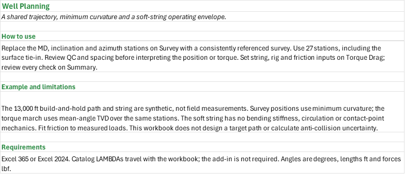
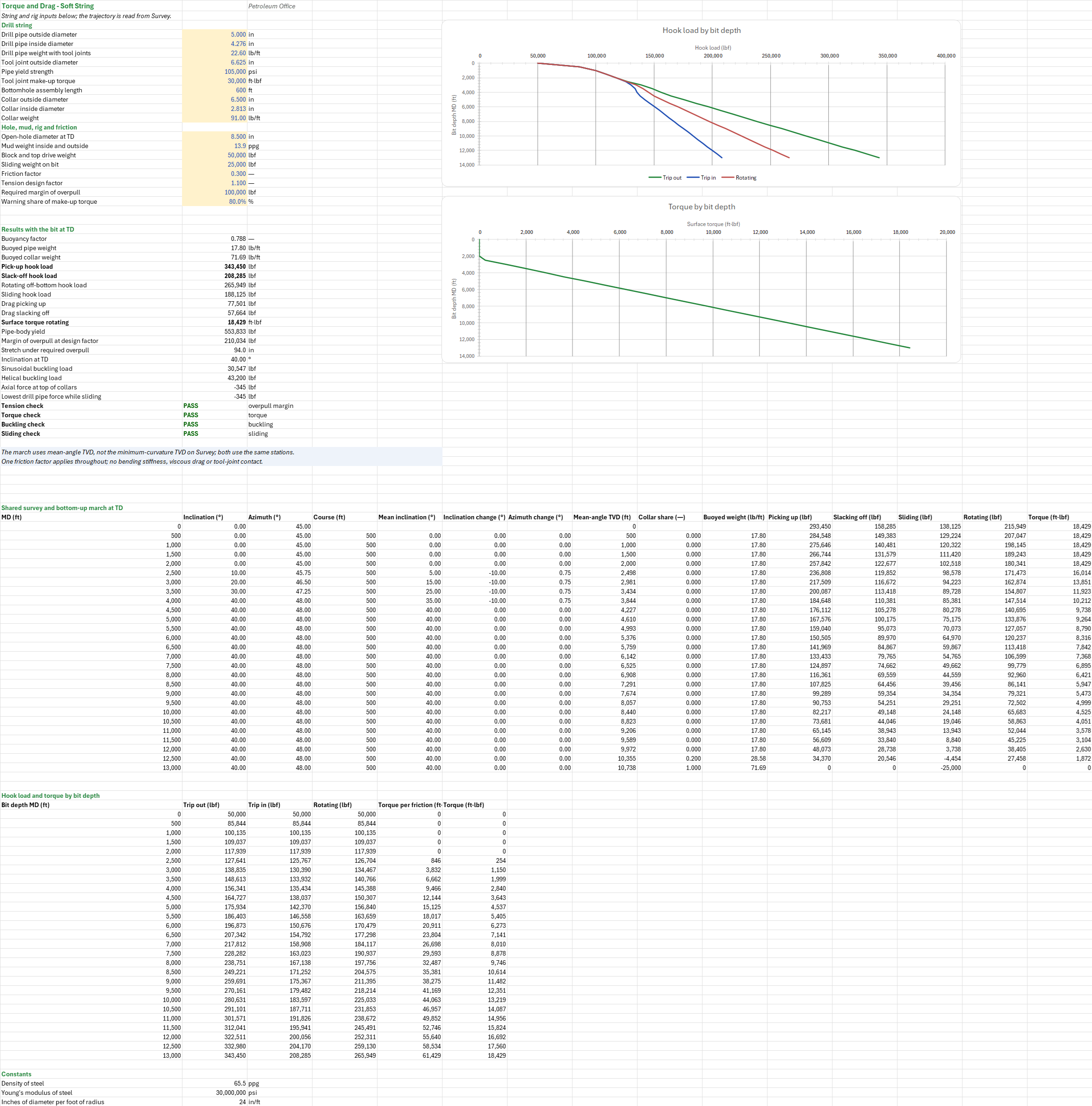
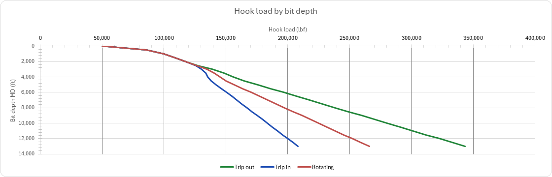
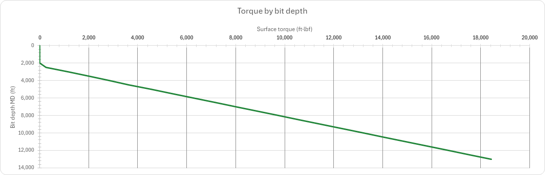
Where does the well go, and can the string be tripped, slid and rotated to TD within its limits? You enter one table of survey stations (MD, inclination and azimuth), the survey limits and north reference, the drill pipe and collars, the mud, the rig and one friction factor. You read off the minimum-curvature TVD, coordinates, vertical section, closure and dogleg at each station, and the hook load and surface torque against bit depth for tripping out and in, sliding and rotating, with checks on buckling, overpull and make-up torque. Field units; no add-in needed.
How to use it: Replace the 27 shared stations on the Survey sheet, including surface, with the planned or measured trajectory; MD must increase, inclinations lie between 0 and 180 degrees and azimuths between 0 and 360 degrees. All azimuths must use the same north. Set the survey criteria and the north reference on Survey, and the actual string, mud, rig and design limits on Torque Drag. Fit the friction factor to measured hook loads and torque. Review every check on the Summary and the source values before relying on the calculation. This is not an automatic target-path design.
Method: Minimum curvature uses the dogleg, the ratio factor and the endpoint inclinations and azimuths to accumulate TVD and horizontal coordinates. The survey reports closure on station, true and grid north. Johancsik's soft-string march integrates from the bit upward, adding the buoyed axial weight and the friction on the normal force for trip out, subtracting it for trip in, and accumulating its moment while rotating. At each shallower bit depth it repeats that march with the collars above the bit. The torque march uses the source blueprint's mean-angle TVD, which is not interchangeable with minimum-curvature TVD, but uses exactly the same MD, inclination and azimuth stations. A single friction factor controls both profiles. The sliding force is checked against sinusoidal and helical buckling, pick-up against pipe-body yield with the design factor and overpull, and surface torque against the tool-joint make-up torque.
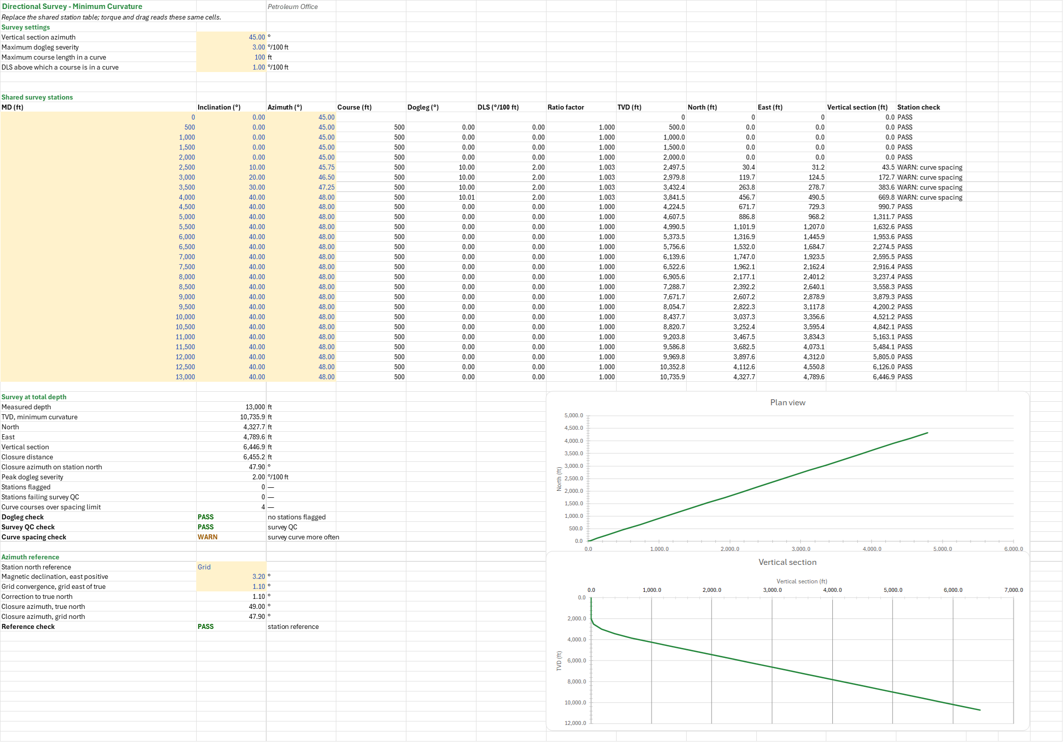
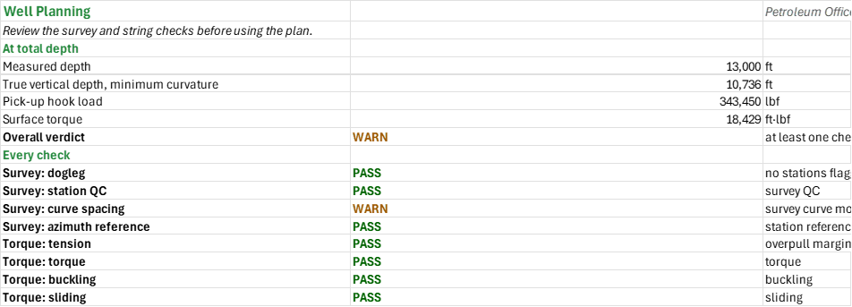
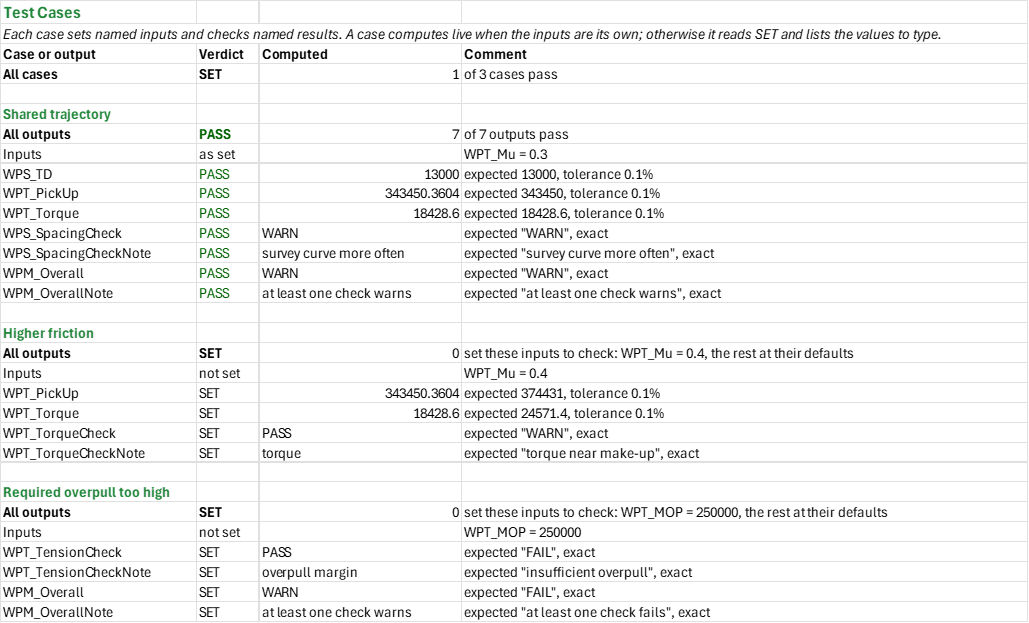
Example: The synthetic drilling-family reference well has 27 stations from surface to 13,000 ft MD, a 2,000 ft kick-off and build to 40 degrees at 4,000 ft. It uses 13.9 ppg mud and 5-in drill pipe over 600 ft of collars. With a friction factor of 0.3, the torque blueprint's matching example gives approximately 343,450 lbf pick-up and 18,429 ft-lbf surface torque. The 500 ft station spacing in the build exceeds the 100 ft curve-spacing criterion, so the survey warns even where the mechanical checks pass.
Validity
The well and survey are synthetic, not independent field validation. Sparse stations smooth doglegs: survey more frequently in curves. Minimum curvature is not a survey uncertainty or anti-collision model. The soft string omits bending stiffness, tool-joint contact, viscous drag and circulation, and uses one friction factor and the same mud inside and out. The buckling check applies the TD inclination and open-hole clearance to the drill pipe; it does not model lock-up or added buckling drag. The torque march uses the shortest signed azimuth change across north. Pipe-body yield is not a connection rating. Use actual pipe and connection specifications and calibrate to rig measurements. The workbook does not design a target path (build and turn planning); the add-in has no function for it.
References
- Sawaryn, S.J. and Thorogood, J.L. (2005). A Compendium of Directional Calculations Based on the Minimum Curvature Method. SPE-84246-PA.
- Johancsik, C.A., Friesen, D.B. and Dawson, R. (1984). Torque and Drag in Directional Wells: Prediction and Measurement. SPE-11380-PA.
- Dawson, R. and Paslay, P.R. (1984). Drillpipe Buckling in Inclined Holes. SPE-11167-PA.
Inputs
| Input | Unit | Default | Name |
|---|---|---|---|
| Survey table: MD, inclination and azimuth at 27 shared stations | ft, deg, deg | 0 to 13000, 0 to 40, 45 to 48 | — |
| Vertical section azimuth | deg | 45 | WPS_VSAzi |
| Maximum dogleg severity | deg/100 ft | 3 | WPS_DLSmax |
| Maximum course length in a curve | ft | 100 | WPS_CLmax |
| DLS above which a course is in a curve | deg/100 ft | 1 | WPS_DLScurve |
| Station north reference (True, Grid or Magnetic) | — | Grid | WPS_AziRef |
| Magnetic declination, east positive | deg | 3.2 | WPS_Decl |
| Grid convergence, grid east of true | deg | 1.1 | WPS_Conv |
| Drill pipe outside diameter | in | 5 | WPT_DpOD |
| Drill pipe inside diameter | in | 4.276 | WPT_DpID |
| Drill pipe weight with tool joints | lb/ft | 22.6 | WPT_DpW |
| Tool joint outside diameter | in | 6.625 | WPT_TjOD |
| Pipe yield strength | psi | 105000 | WPT_Yp |
| Bottomhole assembly length | ft | 600 | WPT_BhaL |
| Collar outside diameter | in | 6.5 | WPT_BhaOD |
| Collar inside diameter | in | 2.8125 | WPT_BhaID |
| Collar weight | lb/ft | 91 | WPT_BhaW |
| Open-hole diameter at TD | in | 8.5 | WPT_Hole |
| Mud weight inside and outside | ppg | 13.9 | WPT_MW |
| Block and top drive weight | lbf | 50000 | WPT_Block |
| Sliding weight on bit | lbf | 25000 | WPT_WOB |
| Friction factor | — | 0.3 | WPT_Mu |
| Tool joint make-up torque | ft-lbf | 30000 | WPT_MakeUp |
| Tension design factor | — | 1.1 | WPT_DFt |
| Required margin of overpull | lbf | 100000 | WPT_MOP |
| Warning share of make-up torque | — | 0.8 | WPT_TorqueWarn |
Sheets
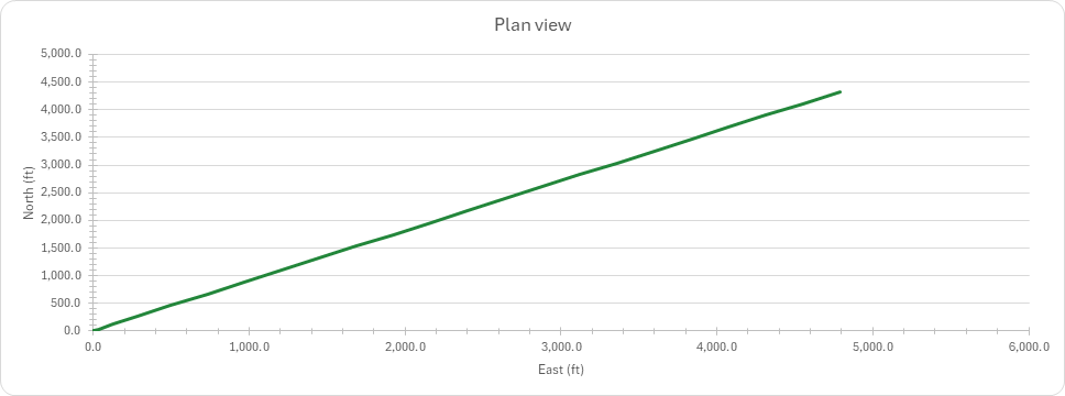
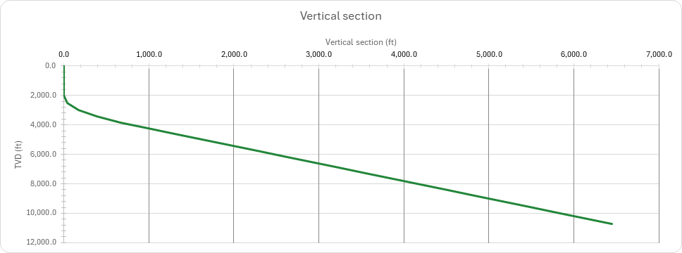
Guide— what the workbook answers and the order to work through its sheets.Survey— the editable station table, minimum-curvature TVD, north, east, vertical section, closure and dogleg, each station's checks, the north reference, and the plan view and vertical section charts.Torque Drag— the same stations with the string, mud and rig: buoyed string weights, the bottom-up march at TD for tripping out and in, sliding and rotating, the buckling, overpull and make-up torque checks, and hook load and torque charted against bit depth.Summary— every named check under one fail-closed verdict.Test Cases— the worked example and other cases, with expected and computed results.
Four charts: the plan view, the vertical section, hook load by bit depth and torque by bit depth.
Functions used
Names (107)
| Name | Refers to | Comment |
|---|---|---|
PO.DE.Casing.Axial.YieldLAMBDA |
=LAMBDA(BodyOD_in, BodyWall_in, BodyYp_psi, PI()/4*(BodyOD_in^2-(BodyOD_in-2*BodyWall_in)^2)*BodyYp_psi) |
API TR 5C3 pipe-body yield strength, Fy = (pi/4)(D^2 - d^2) Yp, [lbf]. |
PO.DE.Dir.ClosureAzimuthLAMBDA |
=LAMBDA(North_ft, East_ft, IF(AND(North_ft = 0, East_ft = 0), 0, MOD(DEGREES(ATAN2(North_ft, East_ft)), 360))) |
Closure azimuth, degrees from north (0-360), of the horizontal displacement from the surface location. |
PO.DE.Dir.ClosureDistanceLAMBDA |
=LAMBDA(North_ft, East_ft, SQRT(North_ft^2 + East_ft^2)) |
Closure distance, ft: the straight-line horizontal displacement from the surface location. |
PO.DE.Dir.DoglegSeverityLAMBDA |
=LAMBDA(Inc1_deg, Azi1_deg, Inc2_deg, Azi2_deg, dMD_ft, DEGREES(2 * ASIN(SQRT(MIN(1, SIN(RADIANS(Inc2_deg - Inc1_deg) / 2)^2 + SIN(RADIANS(Inc1_deg)) * SIN(RADIANS(Inc2_deg)) * SIN(RADIANS(Azi2_deg - Azi1_deg) / 2)^2)))) * 100 / dMD_ft) |
Dogleg severity in degrees per 100 ft between two directional surveys, from the inclinations, azimuths and course length. |
PO.DE.Dir.MinCurv.dEastLAMBDA |
=LAMBDA(Inc1_deg, Azi1_deg, Inc2_deg, Azi2_deg, dMD_ft, RF, dMD_ft / 2 * (SIN(RADIANS(Inc1_deg)) * SIN(RADIANS(Azi1_deg)) + SIN(RADIANS(Inc2_deg)) * SIN(RADIANS(Azi2_deg))) * RF) |
Minimum curvature east increment, ft, over a course. |
PO.DE.Dir.MinCurv.dNorthLAMBDA |
=LAMBDA(Inc1_deg, Azi1_deg, Inc2_deg, Azi2_deg, dMD_ft, RF, dMD_ft / 2 * (SIN(RADIANS(Inc1_deg)) * COS(RADIANS(Azi1_deg)) + SIN(RADIANS(Inc2_deg)) * COS(RADIANS(Azi2_deg))) * RF) |
Minimum curvature north increment, ft, over a course. |
PO.DE.Dir.MinCurv.dTVDLAMBDA |
=LAMBDA(Inc1_deg, Inc2_deg, dMD_ft, RF, dMD_ft / 2 * (COS(RADIANS(Inc1_deg)) + COS(RADIANS(Inc2_deg))) * RF) |
Minimum curvature TVD increment, ft, over a course. |
PO.DE.Dir.RatioFactorLAMBDA |
=LAMBDA(Dogleg_deg, IF(Dogleg_deg < 0.000001, 1, 2 / RADIANS(Dogleg_deg) * TAN(RADIANS(Dogleg_deg) / 2))) |
Minimum curvature ratio factor from the dogleg angle over a course, degrees (1 for a straight course). |
PO.DE.Dir.VerticalSectionLAMBDA |
=LAMBDA(North_ft, East_ft, VSAzi_deg, North_ft * COS(RADIANS(VSAzi_deg)) + East_ft * SIN(RADIANS(VSAzi_deg))) |
Vertical section, ft: the horizontal displacement projected onto the vertical section azimuth. |
PO.DE.TD.Buckling.HelicalLAMBDA |
=LAMBDA(OD_in, ID_in, Dh_in, Wb_lbft, Inc_deg, E_psi, Mode, LET(mi, PI()/64*(OD_in^4 - ID_in^4), wpi, Wb_lbft/12, IF(Mode=1, 5.55*(E_psi*mi*wpi^2)^(1/3), 2*SQRT(2)*SQRT(E_psi*mi*wpi*SIN(RADIANS(Inc_deg))/((Dh_in - OD_in)/2))))) |
Helical buckling load, lbf: the square root of 2 times Dawson-Paslay in an inclined hole (Mode 0) or 5.55 (EI w^2)^(1/3) in a vertical one (Mode 1). |
PO.DE.TD.Buckling.SinusoidalLAMBDA |
=LAMBDA(OD_in, ID_in, Dh_in, Wb_lbft, Inc_deg, E_psi, Mode, LET(mi, PI()/64*(OD_in^4 - ID_in^4), wpi, Wb_lbft/12, IF(Mode=1, 1.94*(E_psi*mi*wpi^2)^(1/3), 2*SQRT(E_psi*mi*wpi*SIN(RADIANS(Inc_deg))/((Dh_in - OD_in)/2))))) |
Sinusoidal buckling load, lbf: Dawson-Paslay in an inclined hole (Mode 0) or Lubinski 1.94 (EI w^2)^(1/3) in a vertical one (Mode 1). |
PO.DE.TD.BuoyancyLAMBDA |
=LAMBDA(PipeW_lbft, PipeOD_in, PipeID_in, MWi_ppg, MWo_ppg, RhoSteel_ppg, LET(bf, 1 - (MWo_ppg*PipeOD_in^2 - MWi_ppg*PipeID_in^2) / (RhoSteel_ppg*(PipeOD_in^2 - PipeID_in^2)), HSTACK(bf, PipeW_lbft*bf))) |
Buoyancy factor of a pipe with different fluids inside and outside, and its buoyed weight per foot: {BF, lb/ft}. |
PO.DE.TD.StretchLAMBDA |
=LAMBDA(F_lbf, W_lbft, L_ft, OD_in, ID_in, E_psi, 12*L_ft*(F_lbf + W_lbft*L_ft/2) / (E_psi*PI()/4*(OD_in^2 - ID_in^2))) |
Hooke stretch of a pipe string, in., under an end load plus its own weight: 12 L (F + w L / 2) / (E As). |
WPM_Checks |
Summary!$B$10:$B$17 |
Every named survey and torque check |
WPM_Overall |
Summary!$B$8 |
Overall verdict verdict |
WPM_OverallNote |
Summary!$C$8 |
Overall verdict comment |
WPM_PickUp |
Summary!$B$6 |
Pick-up hook load, lbf |
WPM_Results |
Summary!$B$4:$B$7 |
Headline results from the shared survey and torque calculation |
WPM_TD |
Summary!$B$4 |
Measured depth, ft |
WPM_TVD |
Summary!$B$5 |
True vertical depth, minimum curvature, ft |
WPM_Torque |
Summary!$B$7 |
Surface torque, ft·lbf |
WPS_AziRef |
Survey!$B$57 |
Station north reference |
WPS_CLmax |
Survey!$B$6 |
Maximum course length in a curve, ft |
WPS_Closure |
Survey!$B$46 |
Closure distance, ft |
WPS_ClosureAzi |
Survey!$B$47 |
Closure azimuth on station north, ° |
WPS_ClosureAziGrid |
Survey!$B$62 |
Closure azimuth, grid north, ° |
WPS_ClosureAziTrue |
Survey!$B$61 |
Closure azimuth, true north, ° |
WPS_Conv |
Survey!$B$59 |
Grid convergence, grid east of true, ° |
WPS_Curve |
Survey!$I$12:$J$38 |
Plan view |
WPS_DLScurve |
Survey!$B$7 |
DLS above which a course is in a curve, °/100 ft |
WPS_DLSmax |
Survey!$B$5 |
Maximum dogleg severity, °/100 ft |
WPS_DLSpeak |
Survey!$B$48 |
Peak dogleg severity, °/100 ft |
WPS_Decl |
Survey!$B$58 |
Magnetic declination, east positive, ° |
WPS_DoglegCheck |
Survey!$B$52 |
Dogleg check verdict |
WPS_DoglegCheckNote |
Survey!$C$52 |
Dogleg check comment |
WPS_East |
Survey!$B$44 |
East, ft |
WPS_Flagged |
Survey!$B$49 |
Stations flagged |
WPS_Inputs |
Survey!$B$4:$B$7 |
Survey limits and vertical section direction |
WPS_North |
Survey!$B$43 |
North, ft |
WPS_QCCheck |
Survey!$B$53 |
Survey QC check verdict |
WPS_QCCheckNote |
Survey!$C$53 |
Survey QC check comment |
WPS_QCFlagged |
Survey!$B$50 |
Stations failing survey QC |
WPS_Ref_Inputs |
Survey!$B$57:$B$59 |
Station reference, declination and convergence |
WPS_Ref_Results |
Survey!$B$60:$B$63 |
Closure azimuths and reference check |
WPS_ReferenceCheck |
Survey!$B$63 |
Reference check verdict |
WPS_ReferenceCheckNote |
Survey!$C$63 |
Reference check comment |
WPS_Results |
Survey!$B$41:$B$54 |
Survey position, station quality and checks |
WPS_Section |
Survey!$H$12:$K$38 |
Vertical section |
WPS_Spacing |
Survey!$B$51 |
Curve courses over spacing limit |
WPS_SpacingCheck |
Survey!$B$54 |
Curve spacing check verdict |
WPS_SpacingCheckNote |
Survey!$C$54 |
Curve spacing check comment |
WPS_Survey |
Survey!$A$12:$C$38 |
Survey stations: measured depth, inclination, azimuth |
WPS_TD |
Survey!$B$41 |
Measured depth, ft |
WPS_TVD |
Survey!$B$42 |
TVD, minimum curvature, ft |
WPS_VS |
Survey!$B$45 |
Vertical section, ft |
WPS_VSAzi |
Survey!$B$4 |
Vertical section azimuth, ° |
WPT_BF |
'Torque Drag'!$B$26 |
Buoyancy factor |
WPT_BhaID |
'Torque Drag'!$B$12 |
Collar inside diameter, in |
WPT_BhaL |
'Torque Drag'!$B$10 |
Bottomhole assembly length, ft |
WPT_BhaOD |
'Torque Drag'!$B$11 |
Collar outside diameter, in |
WPT_BhaW |
'Torque Drag'!$B$13 |
Collar weight, lb/ft |
WPT_Block |
'Torque Drag'!$B$17 |
Block and top drive weight, lbf |
WPT_BucklingCheck |
'Torque Drag'!$B$46 |
Buckling check verdict |
WPT_BucklingCheckNote |
'Torque Drag'!$C$46 |
Buckling check comment |
WPT_Curve |
'Torque Drag'!$A$88:$F$114 |
Hook load and surface torque at each bit depth |
WPT_DFt |
'Torque Drag'!$B$20 |
Tension design factor |
WPT_DiaFt |
'Torque Drag'!$B$119 |
Inches of diameter per foot of radius, in/ft |
WPT_DpID |
'Torque Drag'!$B$5 |
Drill pipe inside diameter, in |
WPT_DpOD |
'Torque Drag'!$B$4 |
Drill pipe outside diameter, in |
WPT_DpW |
'Torque Drag'!$B$6 |
Drill pipe weight with tool joints, lb/ft |
WPT_DragIn |
'Torque Drag'!$B$34 |
Drag slacking off, lbf |
WPT_DragOut |
'Torque Drag'!$B$33 |
Drag picking up, lbf |
WPT_E |
'Torque Drag'!$B$118 |
Young's modulus of steel, psi |
WPT_FBha |
'Torque Drag'!$B$42 |
Axial force at top of collars, lbf |
WPT_Fhel |
'Torque Drag'!$B$41 |
Helical buckling load, lbf |
WPT_Fmin |
'Torque Drag'!$B$43 |
Lowest drill pipe force while sliding, lbf |
WPT_Fsin |
'Torque Drag'!$B$40 |
Sinusoidal buckling load, lbf |
WPT_Hole |
'Torque Drag'!$B$15 |
Open-hole diameter at TD, in |
WPT_IncTD |
'Torque Drag'!$B$39 |
Inclination at TD, ° |
WPT_Inputs |
'Torque Drag'!$B$4:$B$22 |
Drill string, mud, rig and design limits |
WPT_MOP |
'Torque Drag'!$B$21 |
Required margin of overpull, lbf |
WPT_MW |
'Torque Drag'!$B$16 |
Mud weight inside and outside, ppg |
WPT_MakeUp |
'Torque Drag'!$B$9 |
Tool joint make-up torque, ft·lbf |
WPT_March |
'Torque Drag'!$A$57:$O$83 |
Linked stations, mean-angle geometry, forces and torque at TD |
WPT_Mu |
'Torque Drag'!$B$19 |
Friction factor |
WPT_Overpull |
'Torque Drag'!$B$37 |
Margin of overpull at design factor, lbf |
WPT_PickUp |
'Torque Drag'!$B$29 |
Pick-up hook load, lbf |
WPT_Results |
'Torque Drag'!$B$26:$B$47 |
Loads, torque, strength, buckling and checks at TD |
WPT_Rotating |
'Torque Drag'!$B$31 |
Rotating off-bottom hook load, lbf |
WPT_SlackOff |
'Torque Drag'!$B$30 |
Slack-off hook load, lbf |
WPT_SlideCheck |
'Torque Drag'!$B$47 |
Sliding check verdict |
WPT_SlideCheckNote |
'Torque Drag'!$C$47 |
Sliding check comment |
WPT_Sliding |
'Torque Drag'!$B$32 |
Sliding hook load, lbf |
WPT_Steel |
'Torque Drag'!$B$117 |
Density of steel, ppg |
WPT_Stretch |
'Torque Drag'!$B$38 |
Stretch under required overpull, in |
WPT_TensionCheck |
'Torque Drag'!$B$44 |
Tension check verdict |
WPT_TensionCheckNote |
'Torque Drag'!$C$44 |
Tension check comment |
WPT_TjOD |
'Torque Drag'!$B$7 |
Tool joint outside diameter, in |
WPT_Torque |
'Torque Drag'!$B$35 |
Surface torque rotating, ft·lbf |
WPT_TorqueCheck |
'Torque Drag'!$B$45 |
Torque check verdict |
WPT_TorqueCheckNote |
'Torque Drag'!$C$45 |
Torque check comment |
WPT_TorqueWarn |
'Torque Drag'!$B$22 |
Warning share of make-up torque, % |
WPT_WOB |
'Torque Drag'!$B$18 |
Sliding weight on bit, lbf |
WPT_WbBha |
'Torque Drag'!$B$28 |
Buoyed collar weight, lb/ft |
WPT_WbDp |
'Torque Drag'!$B$27 |
Buoyed pipe weight, lb/ft |
WPT_Yield |
'Torque Drag'!$B$36 |
Pipe-body yield, lbf |
WPT_Yp |
'Torque Drag'!$B$8 |
Pipe yield strength, psi |
Details
| Opens in | Needs Microsoft 365 or Excel 2024: it uses functions Excel 2016 doesn't have, such as named LAMBDAs, which show #NAME? there. |
| File | WellPlanning.xlsx, 69 KB |
| Category | Drilling |
| For agents and tools | Descriptor (.md) |