Multiphase Flowline by Beggs and Brill
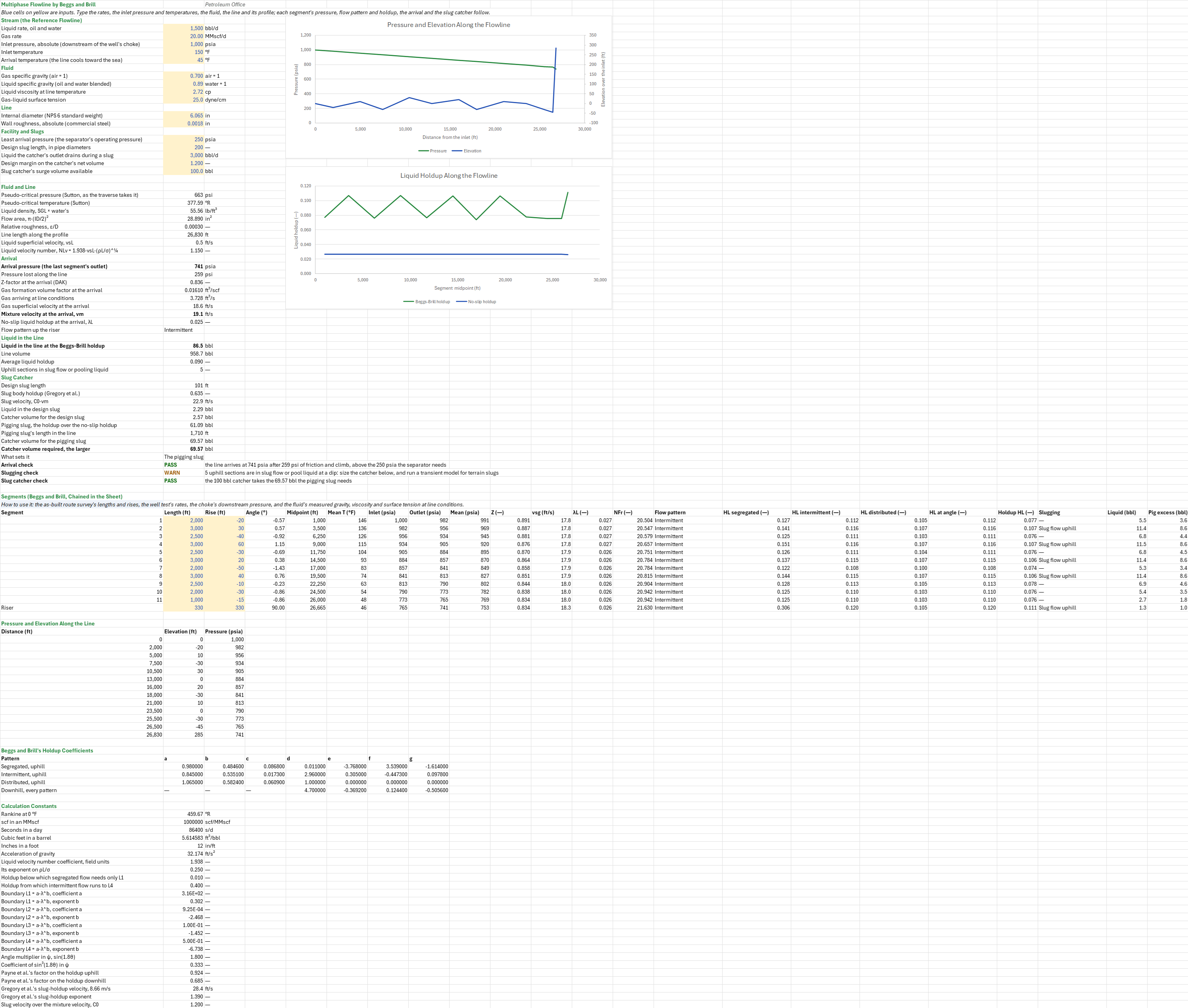
Description
What pressure does a gas-liquid flowline arrive at over hilly ground, how much liquid does it hold, and how big a slug catcher does it need? You enter the liquid and gas rates, the inlet pressure and temperatures, the fluid, the line's diameter and roughness, each segment's length and rise, and the facility's pressure and slug design. You read off the arrival pressure, each segment's flow pattern and holdup, the liquid in the line, the uphill sections in slug flow, and the catcher volume the design slug and the pigging slug need.
Parameters:
- Stream: the liquid and gas rates
MFL_QL,MFL_Qg, the inlet pressureMFL_Pin, and the inlet and arrival temperaturesMFL_Tin,MFL_Tout - Fluid: the gas gravity
MFL_SG, the liquid gravityMFL_SGL, its viscosityMFL_ULand the surface tensionMFL_IFT - Line: the internal diameter
MFL_IDand the absolute roughnessMFL_Eps; each segment's length and rise in the segment table - Facility and slugs: the least arrival pressure
MFL_Pmin, the design slug in pipe diametersMFL_Nslug, the catcher's drain rateMFL_Drain, the design marginMFL_Marginand the catcher's surge volumeMFL_Vcatch
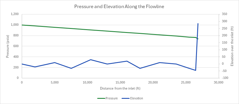
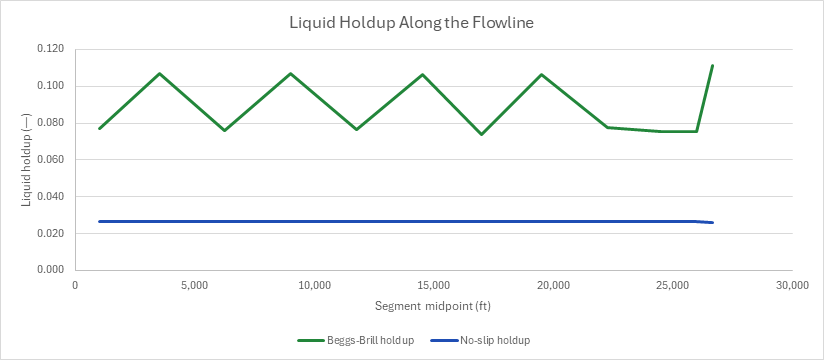
How to use it: Take the segment lengths and rises from the as-built route survey, the rates from a well test, the inlet pressure from the gauge downstream of the choke, and the arrival temperature from the topsides gauge. Measure the liquid's gravity and viscosity at line temperature (an emulsion's when water rides in the oil). A design slug from a slug-length study or a transient run replaces the 200 diameters. The sheet runs Beggs and Brill along the elevation profile as a chain of segments, each from the outlet pressure of the one before, at its own angle and mean temperature, and writes each segment's flow pattern and holdup in cells. It flags the uphill sections in slug flow, or where liquid pools at a dip. The gas rate and velocities at the arrival follow. The slug catcher is sized twice, for a design slug and for the slug a pig pushes out, and the larger sets it. One chart draws the pressure and the elevation along the line, the other the holdup of each segment.
Method:
- Segments. Each segment's angle is asin(rise/length). Its mean temperature lies on a straight line from the inlet to the arrival temperature, at its midpoint. Its outlet pressure is Beggs and Brill's traverse from its inlet pressure, the outlet of the segment before. The traverse marches the segment in 100 ft steps, with DAK's Z, Lee-Gonzalez-Eakin's gas viscosity and the gas's Bg at Sutton's pseudo-criticals. The liquid's density, viscosity and Bo = 1 are constant.
- Pattern. At each segment's mean pressure and temperature the sheet takes Z (DAK at Sutton's pseudo-criticals, as the traverse does), Bg, the gas superficial velocity vsg and the liquid's vsL. From them it takes the no-slip holdup λL = vsL/(vsL + vsg) and the Froude number NFr = vm²/(g·D). Beggs and Brill's map places the pattern by NFr against the boundaries L1 = 316·λ^0.302, L2 = 0.0009252·λ^−2.4684, L3 = 0.1·λ^−1.4516 and L4 = 0.5·λ^−6.738.
- Holdup. For each pattern HL(0) = a·λ^b/NFr^c, not below λ. At the segment's angle it is HL(0)·ψ, ψ = 1 + C·(sin 1.8θ − 0.333·sin³ 1.8θ) and C = (1 − λ)·ln(d·λ^e·NLv^f·NFr^g), not below 0, with NLv = 1.938·vsL·(ρL/σ)^¼. The coefficients are the table's, by pattern uphill and one set downhill. In the transition the holdup is A·HL,seg + (1 − A)·HL,int, with A = (L3 − NFr)/(L3 − L2). Payne et al.'s factor then takes 0.924 of it uphill and 0.685 downhill, and uphill it is not below λ.
- Flags. An uphill segment in intermittent or transition flow is in slug flow. An uphill segment in segregated flow after a downhill one is a terrain-slug risk: liquid pools at the dip until the gas pushes it up.
- Liquid and pigging. The liquid in the line is the sum of each segment's holdup times its volume. A pig moves at about the mixture velocity, so it pushes out the liquid above the no-slip holdup: the sum of (HL − λL) times each segment's volume.
- Slug catcher. The design slug is the set number of pipe diameters long, at Gregory et al.'s slug-body holdup HLS = 1/(1 + (vm/28.41 ft/s)^1.39), arriving at 1.2·vm. The pigging slug is liquid only, arriving at vm. Each one's catcher volume is the margin times its liquid less what the outlet drains while it arrives; the larger sets the catcher.
- Checks.
- Arrival: the line arrives at or above the separator's pressure.
- Slugging: no uphill section is flagged.
- Slug catcher: the catcher holds the larger slug.
Example: The default case is the flow-assurance family's reference flowline: 20 MMscf/d of the 0.7 gravity gas and 1,500 bbl/d of liquid (1,000 STB/d of the reference oil and 500 bbl/d of water, 0.89 gravity blended). It runs in 6-in standard-weight pipe (6.065 in), commercial steel at 0.0018 in. It enters at 1,000 psia, the choke sheet's downstream pressure, and 150 °F, and cools to 45 °F at the arrival. The liquid's 2.72 cp is the liquid pipeline sheet's, Beal's dead-oil viscosity at 100 °F, near the line's mean temperature. The 25 dyne/cm surface tension is the vertical-lift sheets'. The route is 5 miles of undulating seabed in eleven segments, 20 to 60 ft up or down each, and a 330 ft riser to the facility, whose separator runs at 250 psia (the Separator Sizing by Souders-Brown and Retention Time sheet). The design slug is 200 pipe diameters, the catcher's outlet drains 3,000 bbl/d during a slug, twice the line's liquid rate, the margin is 1.2, and the catcher holds 100 bbl.
The liquid moves at 0.486 ft/s superficially and the gas at 17.8 to 18.3 ft/s, so λL is 0.026 and NFr 20.5 to 21.6: intermittent flow in every segment. The line loses 259 psi and arrives at 740.7 psia, above the separator's 250 psia. The holdup is 0.074 to 0.078 downhill and 0.106 to 0.107 on the seabed uphill, and 0.111 up the riser, against the no-slip 0.026. The line holds 86.5 bbl of liquid, an average holdup of 0.090. The four seabed climbs and the riser are in slug flow, so the slugging check warns. At the arrival the gas flows 3.73 ft³/s and the mixture moves at 19.07 ft/s. The 200-diameter design slug is 101 ft long and holds 0.635 liquid, 2.29 bbl, so it needs a 2.57 bbl catcher. The pig pushes out 61.09 bbl, a 1,710 ft slug, which with the margin needs 69.57 bbl. The pigging slug sets the catcher, and the 100 bbl one takes it. Halving the gas to 10 MMscf/d puts the line in transition flow; it arrives at 879.8 psia and holds 146.8 bbl, and the pig's 92.2 bbl slug needs 97.3 bbl. In 8-in pipe (7.981 in) the flow is segregated, the line arrives at 898.1 psia and holds 219.5 bbl, and the pigging slug needs 190.9 bbl: the 100 bbl catcher fails.
Functions used
PO.PVT.Ppc.BySutton(SG_gas)
Calculates pseudo-critical pressure of hydrocarbon gas using Sutton (1985) correlation, [psi].
PO.PVT.Tpc.BySutton(SG_gas)
Calculates pseudo-critical temperature of hydrocarbon gas using Sutton (1985) correlation, [degR].
PO.PVT.Rho.Wat.Stn()
Water density at standard conditions, [lb/ft3].
PO.PVT.Z.ByDAK(Ppr, Tpr)
Calculates gas compressibility factor (Z) using Dranchuk and Abou-Kassem (1975) equation of state, [dimensionless].
PO.PVT.Bg.ByDefinition(P, T_degR, Z)
Calculates gas formation volume factor, [rcf/scf].
PO.VFP.BeggsBrill.Pout(Ql, Qg, P_in, T_degF, Rho_l, Ul, SG_gas, IFT_gl, pipe_ID, pipe_length, pipe_roughness, pipe_angle)
Calculates outlet pipe pressure using Beggs and Brill (1973), [psi]. For any wellbore inclination. Gas properties (ρg, μg, Bg) use DAK (Z-factor) and LGE (viscosity).
Names (85)
| Name | Refers to | Comment |
|---|---|---|
PO.SF.Slug.CatcherVolumeLAMBDA |
=LAMBDA(slug_len, d, holdup, v_slug, q_drain, margin, output, IF(OR(slug_len<0, d<=0, holdup<0, holdup>1, v_slug<=0, q_drain<0, margin<1), NA(), LET(slug, slug_len*PI()/4*(d/12)^2*holdup/5.6145833, drained, q_drain/86400*slug_len/v_slug, IF(output="Slug", slug, IF(output="Drained", drained, IF(output="Volume", margin*MAX(0, slug-drained), NA())))))) |
Slug catcher liquid volume (bbl), design-slug method: "Slug" liquid in the slug body, "Drained" liquid the outlet removes while it arrives, or "Volume" = margin*(Slug - Drained), floored at 0. |
MFL_QL |
$B$4 |
Liquid rate, oil and water, bbl/d |
MFL_Qg |
$B$5 |
Gas rate, MMscf/d |
MFL_Pin |
$B$6 |
Inlet pressure, absolute (downstream of the well's choke), psia |
MFL_Tin |
$B$7 |
Inlet temperature, °F |
MFL_Tout |
$B$8 |
Arrival temperature (the line cools toward the sea), °F |
MFL_SG |
$B$10 |
Gas specific gravity (air = 1), air = 1 |
MFL_SGL |
$B$11 |
Liquid specific gravity (oil and water blended), water = 1 |
MFL_UL |
$B$12 |
Liquid viscosity at line temperature, cp |
MFL_IFT |
$B$13 |
Gas-liquid surface tension, dyne/cm |
MFL_ID |
$B$15 |
Internal diameter (NPS 6 standard weight), in |
MFL_Eps |
$B$16 |
Wall roughness, absolute (commercial steel), in |
MFL_Pmin |
$B$18 |
Least arrival pressure (the separator's operating pressure), psia |
MFL_Nslug |
$B$19 |
Design slug length, in pipe diameters |
MFL_Drain |
$B$20 |
Liquid the catcher's outlet drains during a slug, bbl/d |
MFL_Margin |
$B$21 |
Design margin on the catcher's net volume |
MFL_Vcatch |
$B$22 |
Slug catcher's surge volume available, bbl |
MFL_Inputs |
$B$4:$B$22 |
Liquid and gas rates, inlet pressure, inlet and arrival temperatures, gas and liquid gravities, liquid viscosity, surface tension, line diameter and roughness, least arrival pressure, and the design slug, drain rate, margin and catcher volume |
MFL_Ppc |
$B$25 |
Pseudo-critical pressure (Sutton, as the traverse takes it), psi |
MFL_Tpc |
$B$26 |
Pseudo-critical temperature (Sutton), °R |
MFL_RhoL |
$B$27 |
Liquid density, SGL × water's, lb/ft³ |
MFL_A |
$B$28 |
Flow area, π·(ID/2)², in² |
MFL_Rough |
$B$29 |
Relative roughness, ε/D |
MFL_Ltot |
$B$30 |
Line length along the profile, ft |
MFL_vsl |
$B$31 |
Liquid superficial velocity, vsL, ft/s |
MFL_NLv |
$B$32 |
Liquid velocity number, NLv = 1.938·vsL·(ρL/σ)^¼ |
MFL_Pout |
$B$34 |
Arrival pressure (the last segment's outlet), psia |
MFL_dP |
$B$35 |
Pressure lost along the line, psi |
MFL_Zout |
$B$36 |
Z-factor at the arrival (DAK) |
MFL_Bgout |
$B$37 |
Gas formation volume factor at the arrival, ft³/scf |
MFL_Qgout |
$B$38 |
Gas arriving at line conditions, ft³/s |
MFL_vsgout |
$B$39 |
Gas superficial velocity at the arrival, ft/s |
MFL_vm |
$B$40 |
Mixture velocity at the arrival, vm, ft/s |
MFL_LamOut |
$B$41 |
No-slip liquid holdup at the arrival, λL |
MFL_PatOut |
$B$42 |
Flow pattern up the riser |
MFL_Inventory |
$B$44 |
Liquid in the line at the Beggs-Brill holdup, bbl |
MFL_Vline |
$B$45 |
Line volume, bbl |
MFL_HLavg |
$B$46 |
Average liquid holdup |
MFL_Nflag |
$B$47 |
Uphill sections in slug flow or pooling liquid |
MFL_Lslug |
$B$49 |
Design slug length, ft |
MFL_HLS |
$B$50 |
Slug body holdup (Gregory et al.) |
MFL_Vslug |
$B$51 |
Slug velocity, C0·vm, ft/s |
MFL_SlugVol |
$B$52 |
Liquid in the design slug, bbl |
MFL_CatchSlug |
$B$53 |
Catcher volume for the design slug, bbl |
MFL_PigVol |
$B$54 |
Pigging slug, the holdup over the no-slip holdup, bbl |
MFL_Lpig |
$B$55 |
Pigging slug's length in the line, ft |
MFL_CatchPig |
$B$56 |
Catcher volume for the pigging slug, bbl |
MFL_Vreq |
$B$57 |
Catcher volume required, the larger, bbl |
MFL_Governs |
$B$58 |
What sets it |
MFL_ArrivalCheck |
$B$59 |
Arrival check verdict |
MFL_ArrivalCheckNote |
$C$59 |
Arrival check comment |
MFL_SlugCheck |
$B$60 |
Slugging check verdict |
MFL_SlugCheckNote |
$C$60 |
Slugging check comment |
MFL_CatcherCheck |
$B$61 |
Slug catcher check verdict |
MFL_CatcherCheckNote |
$C$61 |
Slug catcher check comment |
MFL_Results |
$B$25:$B$61 |
The pseudo-criticals, liquid density, flow area, roughness, length and liquid velocity, the arrival pressure, gas rate and velocities, the liquid in the line, the design and pigging slugs and the catcher they need, and the three checks |
MFL_Segments |
$A$66:$V$77 |
Each segment's length, rise, angle, midpoint and mean temperature, Beggs-Brill inlet, outlet and mean pressure, Z, gas velocity, no-slip holdup, Froude number, flow pattern, holdup by pattern and at angle, slugging flag, liquid held, pigging excess |
MFL_HLRiser |
$S$77 |
Beggs-Brill liquid holdup in the last segment, the riser |
MFL_Curve |
$A$81:$C$93 |
Distance along the line, elevation over the inlet and Beggs-Brill pressure at the inlet and each segment's end |
MFL_Coefficients |
$A$97:$H$100 |
Beggs and Brill's holdup coefficients: a, b and c for the horizontal holdup and d to g for the inclination factor, uphill by pattern and downhill for every pattern |
MFL_R0 |
$B$103 |
Rankine at 0 °F, °R |
MFL_Scf |
$B$104 |
scf in an MMscf, scf/MMscf |
MFL_Sec |
$B$105 |
Seconds in a day, s/d |
MFL_Ft3Bbl |
$B$106 |
Cubic feet in a barrel, ft³/bbl |
MFL_InFt |
$B$107 |
Inches in a foot, in/ft |
MFL_G |
$B$108 |
Acceleration of gravity, ft/s² |
MFL_KNlv |
$B$109 |
Liquid velocity number coefficient, field units |
MFL_Quarter |
$B$110 |
Its exponent on ρL/σ |
MFL_LamSeg |
$B$111 |
Holdup below which segregated flow needs only L1 |
MFL_LamInt |
$B$112 |
Holdup from which intermittent flow runs to L4 |
MFL_L1a |
$B$113 |
Boundary L1 = a·λ^b, coefficient a |
MFL_L1b |
$B$114 |
Boundary L1 = a·λ^b, exponent b |
MFL_L2a |
$B$115 |
Boundary L2 = a·λ^b, coefficient a |
MFL_L2b |
$B$116 |
Boundary L2 = a·λ^b, exponent b |
MFL_L3a |
$B$117 |
Boundary L3 = a·λ^b, coefficient a |
MFL_L3b |
$B$118 |
Boundary L3 = a·λ^b, exponent b |
MFL_L4a |
$B$119 |
Boundary L4 = a·λ^b, coefficient a |
MFL_L4b |
$B$120 |
Boundary L4 = a·λ^b, exponent b |
MFL_Kpsi |
$B$121 |
Angle multiplier in ψ, sin(1.8θ) |
MFL_Kpsi3 |
$B$122 |
Coefficient of sin³(1.8θ) in ψ |
MFL_PayneUp |
$B$123 |
Payne et al.'s factor on the holdup uphill |
MFL_PayneDn |
$B$124 |
Payne et al.'s factor on the holdup downhill |
MFL_Vgreg |
$B$125 |
Gregory et al.'s slug-holdup velocity, 8.66 m/s, ft/s |
MFL_Egreg |
$B$126 |
Gregory et al.'s slug-holdup exponent |
MFL_C0 |
$B$127 |
Slug velocity over the mixture velocity, C0 |
Details
| Inserts | 127 rows × 22 columns |
| Category | Surface Facilities |
| For agents and tools | Descriptor (.md) |