Fracture Geometry Models Compared
Description
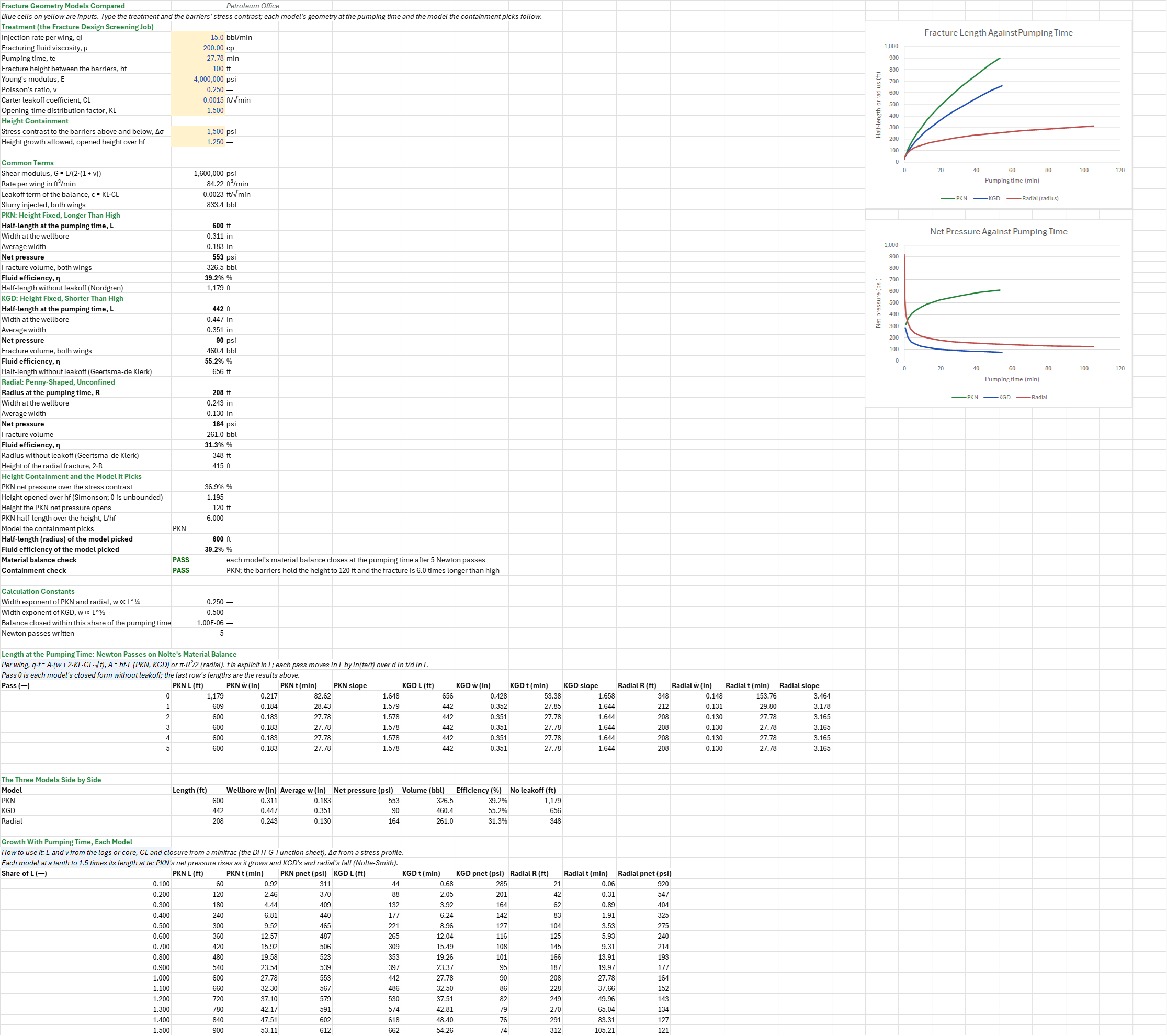
Which 2D fracture model describes this treatment, and how different are the answers? You enter one job (rate, viscosity, pumping time, height, rock moduli and Carter leakoff) and the stress contrast to the barriers. You read off, side by side for PKN, KGD and radial geometries, the half-length or radius, the width at the wellbore and on average, the net pressure, the fracture volume and the fluid efficiency, and which model the height containment picks.
Parameters:
- Treatment: the rate per wing
FGC_Q, the fluid viscosityFGC_Mu, the pumping timeFGC_Te, the fracture height between the barriersFGC_Hf, Young's modulusFGC_E, Poisson's ratioFGC_Nu, Carter's leakoff coefficientFGC_CLand the opening-time factorFGC_KL - Height containment: the stress contrast to the barriers above and below
FGC_Dsig, and the height growth allowed before the fracture counts as uncontainedFGC_HMax
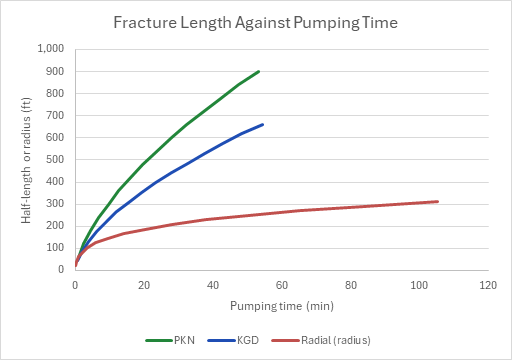
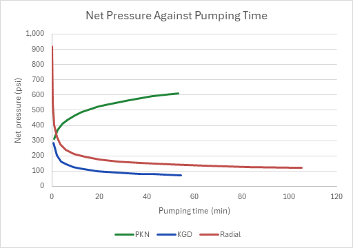
How to use it: Take E and ν from the dipole sonic log or core, CL and the closure stress from a minifrac falloff (the DFIT G-Function Analysis sheet), and Δσ from a stress profile across the barriers. The sheet ships no synthetic data; its inputs are the screening sheet's. It pumps the job for the same time into the three classical geometries: PKN (height fixed, longer than high), KGD (height fixed, shorter than high) and radial (penny-shaped, no barriers). Each model's length at the pumping time comes from Nolte's material balance with Carter leakoff and the model's own width, solved by Newton passes written out as rows. Then the barriers decide: the height that PKN's net pressure would open between symmetric barriers of a given stress contrast (Simonson) says whether the fracture is contained, and the containment picks the model. Two charts draw each model's length and net pressure against pumping time.
Method: Per wing, the slurry pumped fills the fracture and leaks off through both faces: qi·t = A·(w̄ + 2·KL·CL·√t), with A = hf·L for PKN and KGD and π·R²/2 for the radial fracture (Nolte; Economides, Oligney and Valkó, Table 7-4). The average width w̄ is the model's at that length and the treatment rate: the PKN average of the PKN width at (qi, μ, L, E), the KGD average of the KGD width at (2qi, μ, L, hf, G), and the radial average of the radial width at (2qi, μ, R, G), with G = E/(2(1 + ν)). For a given length the balance is a quadratic in √t, √t = (c + √(c² + qa·w̄))/qa with c = KL·CL and qa = qi/A, so t(L) is explicit. Its inverse, the length at the pumping time, takes Newton passes in ln L: with A ∝ L^a and w̄ ∝ L^b (a = 1, b = ¼ for PKN; 1 and ½ for KGD; 2 and ¼ for radial), d ln t/d ln L = ((a + b)·w̄ + 2·a·c·√t)/(qa·t − c·√t), and each pass adds ln(te/t)/that slope. The passes start from each model's closed form without leakoff (Nordgren's PKN, Geertsma-de Klerk's KGD and radial), which the sheet also reports as the bound leakoff pulls the length below. The net pressures and volumes (both wings) are each model's own, and each efficiency is that volume over the slurry injected. For containment, a fracture of height hf between symmetric barriers of contrast Δσ opens to h = hf/sin(π/2·(1 − pnet/Δσ)) (Simonson, Abou-Sayed and Clifton), unbounded once pnet reaches Δσ; with PKN's net pressure, the fracture is contained when h/hf is within the height growth allowed. Contained and at least as long as high is PKN, contained and shorter is KGD, and uncontained is radial.
Example: The default is the job the Fracture Design Screening (Unified Fracture Design) sheet sizes: 15 bbl/min a wing of a 200 cp crosslinked gel into a 100 ft high fracture, E = 4 × 10⁶ psi, ν = 0.25, CL = 0.0015 ft/√min and KL = 1.5, pumped for 27.78 min, the time that sheet's PKN balance takes to its 600 ft design half-length. The barriers carry 1,500 psi more stress than the pay, and a quarter more height than hf still counts as contained.
G = 1.6 × 10⁶ psi and the slurry injected is 30 × 27.78 = 833.4 bbl. From the no-leakoff lengths (1,179, 656 and 348 ft) the balance closes to machine precision by the fourth pass. PKN reaches 600.0 ft at 0.311 in at the wellbore (0.183 in average), a net pressure of 553 psi and an efficiency of 39.2 %: the screening sheet's numbers. KGD reaches 441.5 ft, wider at 0.447 in, with a net pressure of only 90 psi and an efficiency of 55.2 %. The radial fracture reaches a radius of 207.7 ft (415 ft high), 0.243 in wide, at 164 psi and 31.3 %. PKN's 553 psi is 36.9 % of the 1,500 psi contrast, which opens the height to 1.195·hf = 119.5 ft, inside the 1.25 allowed, and the fracture is 6.0 times longer than high: the containment picks PKN.
Functions used
PO.UnitConverter(value, unit_from, unit_to)
Converts value from one unit to another.
PO.FRAC.PKN.Width(Q, Ul, L, E)
Perkins-Kern-Nordgren (PKN) fracture width at wellbore, [in].
PO.FRAC.PKN.Wavg(wMax)
Perkins-Kern-Nordgren (PKN) average fracture width, [in].
PO.FRAC.PKN.Pnet(w, h, E, nu)
Perkins-Kern-Nordgren (PKN) net fracturing pressure, [psi].
PO.FRAC.PKN.Volume(w, h, L)
Perkins-Kern-Nordgren (PKN) fracture volume (one wing), [bbl].
PO.FRAC.Leakoff.Eff(Vfrac, Vtotal)
Fracturing fluid efficiency, [fraction].
PO.FRAC.KGD.Width(Q, Ul, L, h, G)
Khristianovic-Geertsma-de Klerk (KGD) fracture width at wellbore, [in].
PO.FRAC.KGD.Wavg(wMax)
Khristianovic-Geertsma-de Klerk (KGD) average fracture width, [in].
PO.FRAC.KGD.Pnet(ww, L, G)
Khristianovic-Geertsma-de Klerk (KGD) net fracturing pressure, [psi].
PO.FRAC.KGD.Volume(ww, h, L)
Khristianovic-Geertsma-de Klerk (KGD) fracture volume (both wings), [bbl].
PO.FRAC.Radial.Width(Q, Ul, R, G)
Radial (Penny-shaped) fracture width at wellbore, [in].
PO.FRAC.Radial.Wavg(wMax)
Radial (Penny-shaped) fracture average width, [in].
PO.FRAC.Radial.Pnet(ww, R, G, nu)
Radial (Penny-shaped) fracture net pressure, [psi].
PO.FRAC.Radial.Volume(ww, R)
Radial (Penny-shaped) fracture volume, [bbl].
PO.FRAC.PKN.Length.NoLoss(Q, Ul, h, G, nu, t)
Perkins-Kern-Nordgren (PKN) fracture half-length without fluid loss, [ft].
PO.FRAC.KGD.Length.NoLoss(Q, Ul, h, G, t)
Khristianovic-Geertsma-de Klerk (KGD) fracture half-length without fluid loss, [ft].
PO.FRAC.Radial.Radius.NoLoss(Q, Ul, G, t)
Radial (Penny-shaped) fracture radius without fluid loss, [ft].
Names (56)
| Name | Refers to | Comment |
|---|---|---|
FGC_Q |
$B$4 |
Injection rate per wing, qi, bbl/min |
FGC_Mu |
$B$5 |
Fracturing fluid viscosity, μ, cp |
FGC_Te |
$B$6 |
Pumping time, te, min |
FGC_Hf |
$B$7 |
Fracture height between the barriers, hf, ft |
FGC_E |
$B$8 |
Young's modulus, E, psi |
FGC_Nu |
$B$9 |
Poisson's ratio, ν |
FGC_CL |
$B$10 |
Carter leakoff coefficient, CL, ft/√min |
FGC_KL |
$B$11 |
Opening-time distribution factor, KL |
FGC_Dsig |
$B$13 |
Stress contrast to the barriers above and below, Δσ, psi |
FGC_HMax |
$B$14 |
Height growth allowed, opened height over hf |
FGC_Inputs |
$B$4:$B$14 |
The treatment (rate, fluid, pumping time, height, rock and leakoff) and the barriers' stress contrast with the height growth allowed |
FGC_G |
$B$17 |
Shear modulus, G = E/(2·(1 + ν)), psi |
FGC_Qft |
$B$18 |
Rate per wing in ft³/min, ft³/min |
FGC_C |
$B$19 |
Leakoff term of the balance, c = KL·CL, ft/√min |
FGC_Vi |
$B$20 |
Slurry injected, both wings, bbl |
FGC_PknL |
$B$22 |
Half-length at the pumping time, L, ft |
FGC_PknW |
$B$23 |
Width at the wellbore, in |
FGC_PknWavg |
$B$24 |
Average width, in |
FGC_PknPnet |
$B$25 |
Net pressure, psi |
FGC_PknVol |
$B$26 |
Fracture volume, both wings, bbl |
FGC_PknEta |
$B$27 |
Fluid efficiency, η, % |
FGC_PknNoLoss |
$B$28 |
Half-length without leakoff (Nordgren), ft |
FGC_KgdL |
$B$30 |
Half-length at the pumping time, L, ft |
FGC_KgdW |
$B$31 |
Width at the wellbore, in |
FGC_KgdWavg |
$B$32 |
Average width, in |
FGC_KgdPnet |
$B$33 |
Net pressure, psi |
FGC_KgdVol |
$B$34 |
Fracture volume, both wings, bbl |
FGC_KgdEta |
$B$35 |
Fluid efficiency, η, % |
FGC_KgdNoLoss |
$B$36 |
Half-length without leakoff (Geertsma-de Klerk), ft |
FGC_RadR |
$B$38 |
Radius at the pumping time, R, ft |
FGC_RadW |
$B$39 |
Width at the wellbore, in |
FGC_RadWavg |
$B$40 |
Average width, in |
FGC_RadPnet |
$B$41 |
Net pressure, psi |
FGC_RadVol |
$B$42 |
Fracture volume, bbl |
FGC_RadEta |
$B$43 |
Fluid efficiency, η, % |
FGC_RadNoLoss |
$B$44 |
Radius without leakoff (Geertsma-de Klerk), ft |
FGC_RadHeight |
$B$45 |
Height of the radial fracture, 2·R, ft |
FGC_PRatio |
$B$47 |
PKN net pressure over the stress contrast, % |
FGC_HRatio |
$B$48 |
Height opened over hf (Simonson; 0 is unbounded) |
FGC_Height |
$B$49 |
Height the PKN net pressure opens, ft |
FGC_Aspect |
$B$50 |
PKN half-length over the height, L/hf |
FGC_Model |
$B$51 |
Model the containment picks |
FGC_PickL |
$B$52 |
Half-length (radius) of the model picked, ft |
FGC_PickEta |
$B$53 |
Fluid efficiency of the model picked, % |
FGC_SolveCheck |
$B$54 |
Material balance check verdict |
FGC_SolveCheckNote |
$C$54 |
Material balance check comment |
FGC_ModelCheck |
$B$55 |
Containment check verdict |
FGC_ModelCheckNote |
$C$55 |
Containment check comment |
FGC_Results |
$B$17:$B$55 |
The common terms, each model's length, widths, net pressure, volume and efficiency, the height containment, the model picked, and the two checks |
FGC_Quarter |
$B$58 |
Width exponent of PKN and radial, w ∝ L^¼ |
FGC_Half |
$B$59 |
Width exponent of KGD, w ∝ L^½ |
FGC_SolveTol |
$B$60 |
Balance closed within this share of the pumping time |
FGC_Passes |
$B$61 |
Newton passes written |
FGC_Solver |
$A$67:$M$72 |
Newton passes 0 to 5: each model's length (radius), average width, the time the balance gives for it, and d ln t/d ln L |
FGC_Compare |
$A$77:$H$79 |
One row a model: length (radius), widths, net pressure, volume, efficiency and the no-leakoff length |
FGC_Growth |
$A$85:$J$99 |
Each model at 0.1 to 1.5 times its length at te: the length (radius), the pumping time to reach it, and its net pressure |
Details
| Inserts | 99 rows × 13 columns |
| Category | Hydraulic Fracturing |
| For agents and tools | Descriptor (.md) |