Tubing Stress and Movement
Description
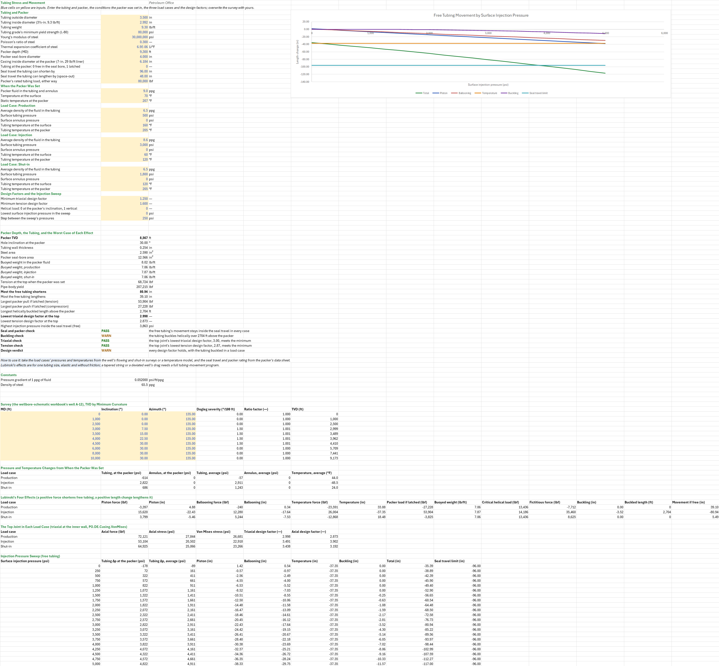
Will the tubing stay in its packer, and hold, when the well goes from the conditions the packer was set in to production, injection or a shut-in? You enter the tubing, the packer and its seal bore, the fluids and temperatures when the packer was set, and each load case's pressures, densities and temperatures. You read off how far free tubing moves against its seal travel, or the load a latched packer takes, whether the tubing buckles, and the top joint's triaxial and tension design factors.
Parameters:
- Tubing and packer: the tubing OD
TS_ODand IDTS_ID(in), its weightTS_W(lb/ft), the grade's yieldTS_Yp, Young's modulusTS_E(psi), Poisson's ratioTS_Nu, the thermal expansion coefficientTS_Beta(1/°F), the packer depthTS_Packer(ft MD), its seal boreTS_Boreand the casing ID at the packerTS_CsgID(in), the modeTS_Mode(0 free in the seal bore, 1 latched), the seal travel upTS_SealUpand downTS_SealDown(in), and the packer's ratingTS_PkRating(lbf) - When the packer was set: the packer fluid
TS_Rho0(ppg) in the tubing and annulus, the surface temperatureTS_Ts0and the static temperature at the packerTS_Tp0(°F) - Load cases: for production (
Prod), injection (Inj) and shut-in (Shut), the tubing fluid's average densityTS_Rho…(ppg), the surface tubing and annulus pressuresTS_Pt…,TS_Pa…(psi), and the tubing temperature at the surface and at the packerTS_Ts…,TS_Tp…(°F) - Design factors and the sweep: the minimum triaxial
TS_DFvmand tensionTS_DFtdesign factors, the helical critical-load modeTS_HelMode(0 at the packer's inclination, 1 vertical), and the sweep's lowest injection pressureTS_StartPand its stepTS_StepP(psi)
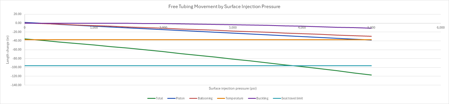
How to use it: The load cases are made up. Take the tubing's pressures and densities from the well's flowing and shut-in gradient surveys or the injection plan, the temperatures from a flowing-temperature model or a temperature log, the seal travel, bore and rating from the packer's data sheet, and the survey from the well's directional survey. The packer's depth comes from the wellbore-schematic workbook's survey, which puts the packer's 9,300 ft MD at its TVD on the minimum-curvature survey, so this sheet and the schematic state the same depth; pressures use the TVD and the tubing's length the MD. The sheet works each of Lubinski's effects in its own cells for each case: the piston force on the tubing's end in the seal bore, ballooning from the average pressure changes, the temperature change, and helical buckling above the packer, from the buoyed weight with the case's fluids and the critical helical load at the packer's inclination. A sweep of the injection pressure charts the free tubing's movement, effect by effect, against the seal travel. Check that free tubing moves less than its seal travel, or that a latched packer's load is under its rating; whether a case buckles the tubing, and whether the helix reaches the surface; and that the top joint's lowest triaxial and tension design factors are over their minimums.
Method: Each load case changes the pressure inside the tubing, the pressure in the annulus and the tubing's temperature, and Lubinski's four effects turn those changes into forces and length changes at the packer. The pressure change inside the tubing at the packer is the surface pressure plus the change of the fluid column, Pt + 0.052 (ρ − ρ0) TVD, and in the annulus the surface pressure. The average changes are the means of the surface and packer values, and the temperature change is the change of the mean of the surface and packer temperatures. The piston force is F1 = (Ap − Ai) ΔPi − (Ap − Ao) ΔPo. Ballooning is F2 = 2ν (ΔPia Ai − ΔPoa Ao). The temperature force is F3 = −E β As ΔT. Each length change is −12 L F / (E As), or 12 L β ΔT for temperature, with L the packer's MD. A positive force shortens free tubing and a positive length change lengthens it, so the effects add. The fictitious force is Ff = Ap (ΔPi − ΔPo), less the packer's load when the tubing is latched. It buckles the tubing above the critical helical load, 2√2 √(E I w sin θ / r) at the packer's inclination θ, with r the radial clearance. Lubinski's buckling then shortens it by r² (Ff² − Fcr²) / (8 E I w), with w the buoyed weight per inch, over a length (Ff − Fcr) / W. The tubing either floats in the seal bore, where it moves by the sum of the four, or is latched, where it puts F1 + F2 + F3 on the packer (Hammerlindl). The top joint carries the landing tension, the buoyed weight times the packer's TVD. Free tubing loses the piston force from it. Latched tubing adds the ballooning and temperature forces the packer holds. The von Mises stress at the inner wall takes Lamé's radial and hoop stresses from the surface pressures. The triaxial design factor is Yp over that stress, and the tension design factor is the pipe-body yield over the axial force. The sweep repeats the injection case at each surface pressure, and the highest pressure the seal travel takes is read straight between the two sweep rows on either side of it.
Example: The wellbore-schematic workbook's well, example well A-12: vertical to a kick-off at 2,500 ft, built at 1.5°/100 ft to 30° at 4,500 ft MD and held to TD at 10,000 ft MD (9,173 ft TVD). The completion is 3½-in. 9.3 lb/ft L-80 tubing (ID 2.992 in.) on a production packer at 9,300 ft MD in the 7-in. 29 lb/ft liner (ID 6.184 in.). The tubing seals in a 4.00-in. bore, free to move, with 96 in. of seal travel up and 48 in. down. The packer was set in the workbook's 9.0 ppg packer fluid, at 70 °F at the surface and 207 °F at the packer. Production flows 6.5 ppg of oil and gas at 500 psi, at 160 °F at the surface and 205 °F at the packer. Injection is 8.6 ppg water at 3,000 psi, at 60 °F and 120 °F. Shut-in leaves 1,800 psi on the 6.5 ppg column, at 120 °F and 205 °F. The annulus stays at 0 psi. The design factors are 1.25 triaxial and 1.6 in tension. The schematic gives the strings' ODs only; the tubing grade, the liner weight, the seal bore and the load cases are this sheet's choices.
The packer sits at 8,567 ft TVD, on the 30° hold. The tubing's steel area is 2.590 in², and the bore's 12.566 in². In the packer fluid it weighs 8.02 lb/ft buoyed, so it hangs 68,724 lbf at the top. Injection puts 2,822 psi more in the tubing at the packer, 2,911 psi more on average, and cools it 48.5 °F. Piston, ballooning and temperature forces of 15,620, 12,280 and 26,004 lbf shorten the free tubing 22.4, 17.6 and 37.3 in. The 35,460 lbf fictitious force is over the 14,186 lbf critical helical load, so the bottom 2,704 ft buckles and shortens it 3.5 in. more, 80.9 in. in all, inside the 96 in. of seal travel. Production heats the tubing 44 °F and lengthens it 39.1 in., inside the 48 in. of space-out. Shut-in moves it 5.5 in. The seal travel holds the injection up to 3,863 psi at the surface. Latched, the same tubing would pull 53,904 lbf on the packer while injecting and push 27,228 lbf while producing. The top joint's lowest triaxial design factor is 3.00, in production, and its lowest tension design factor 2.87. Every design factor holds; the buckled injection case is the one to watch. Latched, the producing tubing buckles over 861 ft instead, and the injection raises the top joint's axial force to 107,008 lbf, a tension design factor of 1.94. J-55 tubing latched and injecting at 5,000 psi fails both: 1.23 triaxial and 1.23 in tension.
Functions used
None: the blueprint calculates with Excel's own functions.
Names (92)
| Name | Refers to | Comment |
|---|---|---|
PO.DE.Dir.DoglegSeverityLAMBDA |
=LAMBDA(Inc1_deg, Azi1_deg, Inc2_deg, Azi2_deg, dMD_ft, DEGREES(2 * ASIN(SQRT(MIN(1, SIN(RADIANS(Inc2_deg - Inc1_deg) / 2)^2 + SIN(RADIANS(Inc1_deg)) * SIN(RADIANS(Inc2_deg)) * SIN(RADIANS(Azi2_deg - Azi1_deg) / 2)^2)))) * 100 / dMD_ft) |
Dogleg severity in degrees per 100 ft between two directional surveys, from the inclinations, azimuths and course length. |
PO.DE.Dir.RatioFactorLAMBDA |
=LAMBDA(Dogleg_deg, IF(Dogleg_deg < 0.000001, 1, 2 / RADIANS(Dogleg_deg) * TAN(RADIANS(Dogleg_deg) / 2))) |
Minimum curvature ratio factor from the dogleg angle over a course, degrees (1 for a straight course). |
PO.DE.Dir.MinCurv.dTVDLAMBDA |
=LAMBDA(Inc1_deg, Inc2_deg, dMD_ft, RF, dMD_ft / 2 * (COS(RADIANS(Inc1_deg)) + COS(RADIANS(Inc2_deg))) * RF) |
Minimum curvature TVD increment, ft, over a course. |
PO.CO.Schematic.DepthsLAMBDA |
=LAMBDA(MD_ft, Survey_MD, Survey_Inc, Survey_Azi, Survey_TVD, LET(n, COUNT(Survey_MD), k, IF(MD_ft < INDEX(Survey_MD, 1), 0, MATCH(MD_ft, Survey_MD, 1)), lo, MAX(1, MIN(k, n - 1)), hi, lo + 1, md_lo, INDEX(Survey_MD, lo), md_hi, INDEX(Survey_MD, hi), inc_lo, RADIANS(INDEX(Survey_Inc, lo)), inc_hi, RADIANS(INDEX(Survey_Inc, hi)), azi_lo, RADIANS(INDEX(Survey_Azi, lo)), azi_hi, RADIANS(INDEX(Survey_Azi, hi)), tvd_lo, INDEX(Survey_TVD, lo), dogleg, 2 * ASIN(SQRT(MIN(1, SIN((inc_hi - inc_lo) / 2)^2 + SIN(inc_lo) * SIN(inc_hi) * SIN((azi_hi - azi_lo) / 2)^2))), frac, (MD_ft - md_lo) / (md_hi - md_lo), cos_at, IF(dogleg < 0.000000001, COS(inc_lo), (SIN((1 - frac) * dogleg) * COS(inc_lo) + SIN(frac * dogleg) * COS(inc_hi)) / SIN(dogleg)), part, frac * dogleg, ratio, IF(part < 0.000000001, 1, 2 / part * TAN(part / 2)), IF(k = 0, tvd_lo - (md_lo - MD_ft), IF(k >= n, INDEX(Survey_TVD, hi) + (MD_ft - md_hi) * COS(inc_hi), tvd_lo + (MD_ft - md_lo) / 2 * (COS(inc_lo) + cos_at) * ratio)))) |
TVD, ft, of a measured depth on a survey: minimum-curvature interpolation between the two stations around it, vertical above the first and straight on below the last. |
PO.DE.TD.BuoyancyLAMBDA |
=LAMBDA(PipeW_lbft, PipeOD_in, PipeID_in, MWi_ppg, MWo_ppg, RhoSteel_ppg, LET(bf, 1 - (MWo_ppg*PipeOD_in^2 - MWi_ppg*PipeID_in^2) / (RhoSteel_ppg*(PipeOD_in^2 - PipeID_in^2)), HSTACK(bf, PipeW_lbft*bf))) |
Buoyancy factor of a pipe with different fluids inside and outside, and its buoyed weight per foot: {BF, lb/ft}. |
PO.DE.TD.Buckling.HelicalLAMBDA |
=LAMBDA(OD_in, ID_in, Dh_in, Wb_lbft, Inc_deg, E_psi, Mode, LET(mi, PI()/64*(OD_in^4 - ID_in^4), wpi, Wb_lbft/12, IF(Mode=1, 5.55*(E_psi*mi*wpi^2)^(1/3), 2*SQRT(2)*SQRT(E_psi*mi*wpi*SIN(RADIANS(Inc_deg))/((Dh_in - OD_in)/2))))) |
Helical buckling load, lbf: the square root of 2 times Dawson-Paslay in an inclined hole (Mode 0) or 5.55 (EI w^2)^(1/3) in a vertical one (Mode 1). |
PO.DE.Casing.VonMisesLAMBDA |
=LAMBDA(WallOD_in, t_in, Pi_psi, Po_psi, Sa_psi, r_in, LET(ro, WallOD_in/2, ri, ro-t_in, k, ro^2-ri^2, mean, (Pi_psi*ri^2-Po_psi*ro^2)/k, dev, (Pi_psi-Po_psi)*ri^2*ro^2/(k*r_in^2), sr, mean-dev, sh, mean+dev, SQRT(((Sa_psi-sr)^2+(sr-sh)^2+(sh-Sa_psi)^2)/2))) |
Triaxial (von Mises) equivalent stress at radius r of a casing wall: Lame radial and hoop stress from internal and external pressure plus the axial stress, [psi]. |
PO.DE.Casing.Axial.YieldLAMBDA |
=LAMBDA(BodyOD_in, BodyWall_in, BodyYp_psi, PI()/4*(BodyOD_in^2-(BodyOD_in-2*BodyWall_in)^2)*BodyYp_psi) |
API TR 5C3 pipe-body yield strength, Fy = (pi/4)(D^2 - d^2) Yp, [lbf]. |
PO.CO.Tubing.PistonLAMBDA |
=LAMBDA(L_ft, OD_in, ID_in, Bore_in, dPi_psi, dPo_psi, E_psi, LET(areaI, PI()/4*ID_in^2, areaO, PI()/4*OD_in^2, areaP, PI()/4*Bore_in^2, frc, (areaP - areaI)*dPi_psi - (areaP - areaO)*dPo_psi, HSTACK(frc, -12*L_ft*frc/(E_psi*(areaO - areaI))))) |
Lubinski piston effect at a packer: the force on the tubing, lbf, and the free-tubing length change, in. (negative shortens): {lbf, in}. |
PO.CO.Tubing.BallooningLAMBDA |
=LAMBDA(L_ft, OD_in, ID_in, dPia_psi, dPoa_psi, E_psi, Nu, LET(areaI, PI()/4*ID_in^2, areaO, PI()/4*OD_in^2, frc, 2*Nu*(dPia_psi*areaI - dPoa_psi*areaO), HSTACK(frc, -12*L_ft*frc/(E_psi*(areaO - areaI))))) |
Lubinski ballooning and reverse ballooning from the average pressure changes inside and outside the tubing: {force lbf, length change in.}. |
PO.CO.Tubing.ThermalLAMBDA |
=LAMBDA(L_ft, OD_in, ID_in, dT_F, E_psi, Beta_perF, LET(steel, PI()/4*(OD_in^2 - ID_in^2), HSTACK(0 - E_psi*Beta_perF*steel*dT_F, 12*L_ft*Beta_perF*dT_F))) |
Lubinski temperature effect from the average tubing temperature change: {force lbf, length change in.}; cooling gives a positive force and a shortening. |
PO.CO.Tubing.BucklingLAMBDA |
=LAMBDA(Ff_lbf, Fcr_lbf, TbgL_ft, TbgOD_in, TbgID_in, CsgID_in, W_lbft, TbgE_psi, LET(mi, PI()/64*(TbgOD_in^4 - TbgID_in^4), clr, (CsgID_in - TbgOD_in)/2, fLow, MAX(Fcr_lbf, Ff_lbf - W_lbft*TbgL_ft), bkl, Ff_lbf > Fcr_lbf, HSTACK(IF(bkl, (fLow^2 - Ff_lbf^2)*clr^2/(8*TbgE_psi*mi*W_lbft/12), 0), IF(bkl, (Ff_lbf - fLow)/W_lbft, 0)))) |
Lubinski helical-buckling length change of tubing, in., above the packer, with the buckled length, ft, from the fictitious force and a critical load. |
TS_OD |
$B$4 |
Tubing outside diameter, in |
TS_ID |
$B$5 |
Tubing inside diameter (3½-in. 9.3 lb/ft), in |
TS_W |
$B$6 |
Tubing weight, lb/ft |
TS_Yp |
$B$7 |
Tubing grade's minimum yield strength (L-80), psi |
TS_E |
$B$8 |
Young's modulus of steel, psi |
TS_Nu |
$B$9 |
Poisson's ratio of steel |
TS_Beta |
$B$10 |
Thermal expansion coefficient of steel, 1/°F |
TS_Packer |
$B$11 |
Packer depth (MD), ft |
TS_Bore |
$B$12 |
Packer seal-bore diameter, in |
TS_CsgID |
$B$13 |
Casing inside diameter at the packer (7-in. 29 lb/ft liner), in |
TS_Mode |
$B$14 |
Tubing at the packer: 0 free in the seal bore, 1 latched |
TS_SealUp |
$B$15 |
Seal travel the tubing can shorten by, in |
TS_SealDown |
$B$16 |
Seal travel the tubing can lengthen by (space-out), in |
TS_PkRating |
$B$17 |
Packer's rated tubing load, either way, lbf |
TS_Rho0 |
$B$19 |
Packer fluid in the tubing and annulus, ppg |
TS_Ts0 |
$B$20 |
Temperature at the surface, °F |
TS_Tp0 |
$B$21 |
Static temperature at the packer, °F |
TS_RhoProd |
$B$23 |
Average density of the fluid in the tubing, ppg |
TS_PtProd |
$B$24 |
Surface tubing pressure, psi |
TS_PaProd |
$B$25 |
Surface annulus pressure, psi |
TS_TsProd |
$B$26 |
Tubing temperature at the surface, °F |
TS_TpProd |
$B$27 |
Tubing temperature at the packer, °F |
TS_RhoInj |
$B$29 |
Average density of the fluid in the tubing, ppg |
TS_PtInj |
$B$30 |
Surface tubing pressure, psi |
TS_PaInj |
$B$31 |
Surface annulus pressure, psi |
TS_TsInj |
$B$32 |
Tubing temperature at the surface, °F |
TS_TpInj |
$B$33 |
Tubing temperature at the packer, °F |
TS_RhoShut |
$B$35 |
Average density of the fluid in the tubing, ppg |
TS_PtShut |
$B$36 |
Surface tubing pressure, psi |
TS_PaShut |
$B$37 |
Surface annulus pressure, psi |
TS_TsShut |
$B$38 |
Tubing temperature at the surface, °F |
TS_TpShut |
$B$39 |
Tubing temperature at the packer, °F |
TS_DFvm |
$B$41 |
Minimum triaxial design factor |
TS_DFt |
$B$42 |
Minimum tension design factor |
TS_HelMode |
$B$43 |
Helical load: 0 at the packer's inclination, 1 vertical |
TS_StartP |
$B$44 |
Lowest surface injection pressure in the sweep, psi |
TS_StepP |
$B$45 |
Step between the sweep's pressures, psi |
TS_Inputs |
$B$4:$B$45 |
The tubing and its steel, the packer, its seal bore and travel and its rating, the conditions it was set in, the three load cases' fluids, pressures and temperatures, the design factors and the sweep |
TS_TVDp |
$B$49 |
Packer TVD, ft |
TS_IncP |
$B$50 |
Hole inclination at the packer, ° |
TS_t |
$B$51 |
Tubing wall thickness, in |
TS_As |
$B$52 |
Steel area, in² |
TS_Ap |
$B$53 |
Packer seal-bore area, in² |
TS_Wb0 |
$B$54 |
Buoyed weight in the packer fluid, lb/ft |
TS_WbProd |
$B$55 |
Buoyed weight, production, lb/ft |
TS_WbInj |
$B$56 |
Buoyed weight, injection, lb/ft |
TS_WbShut |
$B$57 |
Buoyed weight, shut-in, lb/ft |
TS_F0 |
$B$58 |
Tension at the top when the packer was set, lbf |
TS_Fy |
$B$59 |
Pipe-body yield, lbf |
TS_Short |
$B$60 |
Most the free tubing shortens, in |
TS_Long |
$B$61 |
Most the free tubing lengthens, in |
TS_PkTen |
$B$62 |
Largest packer pull if latched (tension), lbf |
TS_PkComp |
$B$63 |
Largest packer push if latched (compression), lbf |
TS_Buckled |
$B$64 |
Longest helically buckled length above the packer, ft |
TS_DFvmMin |
$B$65 |
Lowest triaxial design factor at the top |
TS_DFtMin |
$B$66 |
Lowest tension design factor at the top |
TS_MaxInj |
$B$67 |
Highest injection pressure inside the seal travel (free), psi |
TS_PackerCheck |
$B$68 |
Seal and packer check verdict |
TS_PackerCheckNote |
$C$68 |
Seal and packer check comment |
TS_BucklingCheck |
$B$69 |
Buckling check verdict |
TS_BucklingCheckNote |
$C$69 |
Buckling check comment |
TS_TriaxialCheck |
$B$70 |
Triaxial check verdict |
TS_TriaxialCheckNote |
$C$70 |
Triaxial check comment |
TS_TensionCheck |
$B$71 |
Tension check verdict |
TS_TensionCheckNote |
$C$71 |
Tension check comment |
TS_DesignCheck |
$B$72 |
Design verdict verdict |
TS_DesignCheckNote |
$C$72 |
Design verdict comment |
TS_Results |
$B$49:$B$72 |
The packer's TVD and inclination, the tubing's wall, areas, buoyed weight, landing tension and yield, the worst movement, packer load, buckled length and design factors, the highest injection pressure, and the checks |
TS_Psi |
$B$78 |
Pressure gradient of 1 ppg of fluid, psi/ft/ppg |
TS_Steel |
$B$79 |
Density of steel, ppg |
TS_Survey |
$A$85:$C$94 |
Survey stations: measured depth, inclination, azimuth |
TS_SurveyTvd |
$D$85:$F$94 |
Each station's dogleg severity over the course above it, its ratio factor and its TVD by minimum curvature |
TS_SvMD |
$A$85:$A$94 |
Survey station measured depths, ft |
TS_SvInc |
$B$85:$B$94 |
Survey station inclinations, deg |
TS_SvAzi |
$C$85:$C$94 |
Survey station azimuths, deg |
TS_SvTVD |
$F$85:$F$94 |
Survey station TVDs by minimum curvature, ft |
TS_Changes |
$A$98:$F$100 |
Each load case's pressure changes at the packer and on average in the tubing and the annulus, and its average temperature change |
TS_Effects |
$A$104:$N$106 |
Each load case's piston, ballooning and temperature forces and length changes, the latched packer load, the buoyed weight, the critical helical and fictitious forces, the buckling and the free tubing's movement |
TS_TopJoint |
$A$110:$F$112 |
Each load case's axial force and stress in the top joint, its von Mises stress at the inner wall and its triaxial and axial design factors |
TS_Curve |
$A$116:$I$136 |
Each surface injection pressure: the tubing pressure changes, the free tubing's four length changes, their total and the seal travel limit |
Details
| Inserts | 136 rows × 14 columns |
| Category | Drilling Engineering |
| For agents and tools | Descriptor (.md) |