Plug and Abandonment Design
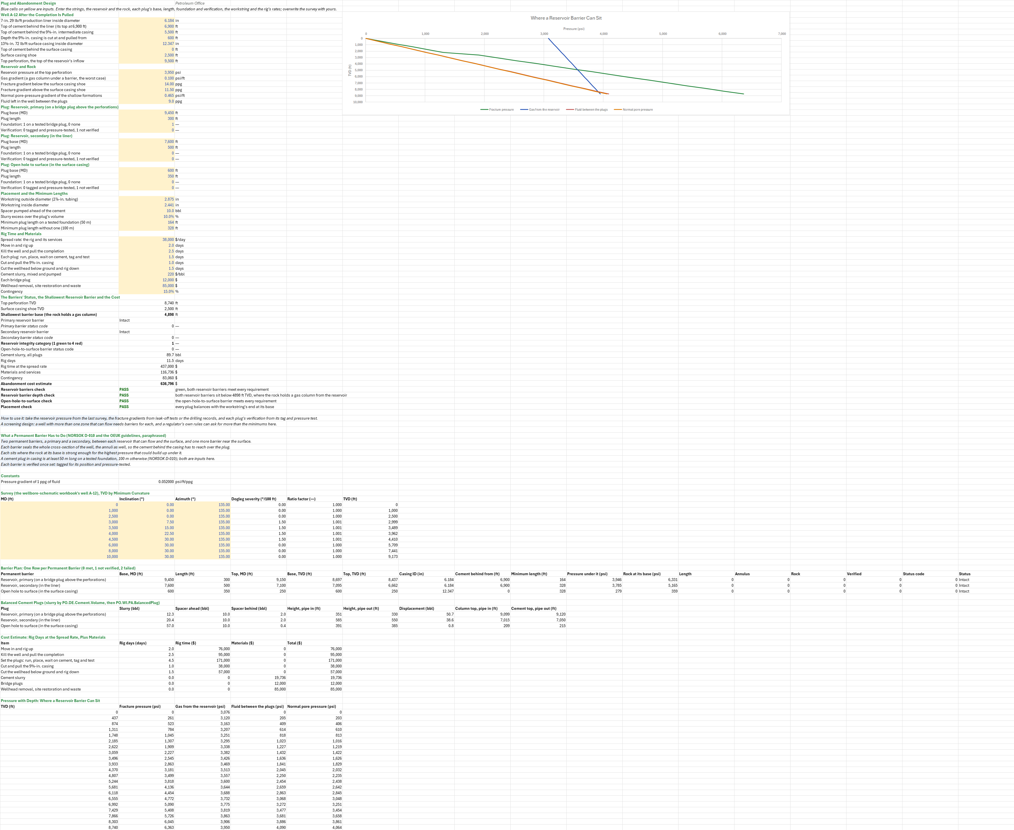
Description
Will the abandonment plan leave the well sealed for good, and what will it cost? You enter the well after the completion is pulled, the reservoir and rock, each cement plug's base, length, foundation and verification, the workstring, and the rig days and prices. You read off each plug's status against NORSOK D-010 and the OEUK guidelines, the green-to-red rating of the reservoir barriers, the shallowest depth a reservoir barrier can sit, each balanced plug's slurry, spacer and displacement, and the cost estimate.
Parameters:
- The well after the completion is pulled: the liner ID
PA_LinerID(in) and the cement behind it fromPA_LinerTOC, the intermediate casing's cement topPA_IntTOC, the depth it is cut at and pulled fromPA_Cut, the surface casing IDPA_SurfID(in), its cement topPA_SurfTOCand its shoePA_SurfShoe, and the top perforationPA_PerfTop(ft MD) - Reservoir and rock: the reservoir pressure
PA_Pres(psi), the gas gradientPA_Ggand the normal pore-pressure gradientPA_Gn(psi/ft), the fracture gradients below and above the surface shoePA_FG,PA_FGs(ppg), and the fluid left between the plugsPA_KillMW(ppg) - Plugs: for the primary
P1, the secondaryP2and the open-hole-to-surface plugP3, the basePA_P…Base(ft MD), the lengthPA_P…Len(ft), the foundationPA_P…Fdn(1 a tested bridge plug, 0 none) and the verificationPA_P…Ver(0 tagged and pressure-tested, 1 not) - Placement and the minimum lengths: the workstring OD and ID
PA_WsOD,PA_WsID(in), the spacer aheadPA_Ahead(bbl), the slurry excessPA_Excess, and the minimum plug lengths with and without a foundationPA_MinFdn,PA_MinOpen(ft) - Rig time and materials: the spread rate
PA_Spread(/bbl), each bridge plug'sPA_BpCost, the fixed costsPA_Fixed($) and the contingencyPA_Cont
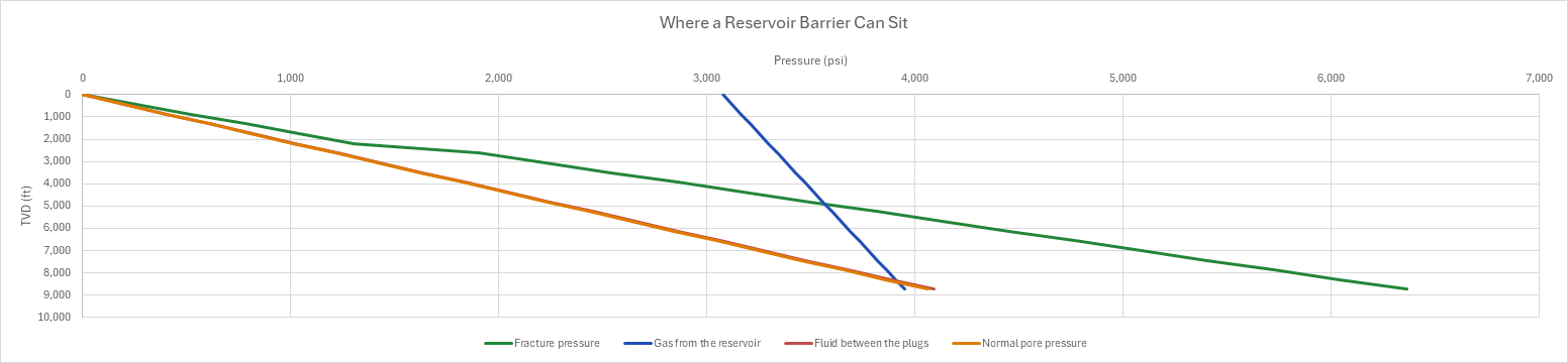
How to use it: The reservoir, the rock and the prices are made up. Take the reservoir pressure from the last pressure survey, the fracture gradients from leak-off tests or the drilling records, the cement tops from the cement bond logs, each plug's verification from its tag and pressure test, and the rates from the rig and service contracts. The minimum lengths and the verification a regulator asks for can differ from NORSOK D-010's: enter its own. The permanent barriers are a table, one row per cement plug, each held to what NORSOK D-010 and the OEUK abandonment guidelines ask of a permanent barrier, paraphrased on the sheet. Each well that can flow from a reservoir needs two barriers between the reservoir and the surface, a primary and a secondary, plus one near the surface against the open hole. Each barrier seals the whole cross-section of the well, the annuli as well as the casing. It sits where the rock at its base can hold the highest pressure that could build up under it. It is long enough, and it is verified once set. Each requirement is an element with a status code, 0 met, 1 not verified and 2 failed. Read the checks: the reservoir check reads the category, green passing, yellow and orange warning, red failing; the depth check fails when a reservoir barrier sits above the shallowest depth; the surface check reads the open-hole-to-surface plug's status; and the placement check warns when a plug's slurry and spacer fill the workstring to surface, leaving nothing to displace. A depth chart draws the fracture pressure, a gas column from the reservoir, the fluid left in the well and the normal pore pressure; the depth where the first two cross is the shallowest a reservoir barrier can sit. The plug depths are put in TVD on the wellbore-schematic workbook's survey, so the plan and the schematic state the same depths.
Method: The shallowest base for a reservoir barrier is where a gas column from the reservoir meets the rock's fracture pressure: 0.052 FG z = Pres − Gg (TVDres − z), so z = (Pres − Gg TVDres) / (0.052 FG − Gg). For each plug the top is the base less the length, and both are put in TVD on the survey by minimum curvature. Four elements follow, each 0 when met and 2 when not. The length element holds the plug to the minimum for its foundation. The annulus element asks that the cement behind the casing start at or above the plug's top; for the surface plug, the 9⅝-in. casing must also be cut at or below the plug's base and above its own cement, so the plug seals the 13⅜-in. casing alone. The rock element compares 0.052 FG × TVD at the plug's base with the pressure under it: a gas column from the reservoir, Pres − Gg (TVDres − TVD), for a reservoir barrier, and the normal pore pressure Gn × TVD for the surface plug. The verification element is 0 when the plug is tagged and pressure-tested and 1 when it is not. The plug's status is its worst element, and the primary's and the secondary's statuses give the category: green with both met, yellow with one not verified, orange with one failed or neither verified, red with one failed and the other not met. Each plug is placed as a balanced plug through an open-ended workstring. Its slurry is the casing's capacity ID²/1029.4 over the plug's length with the excess, sized in its own cell. With the pipe in, the slurry stands as high inside as outside, H = V / (Ca + Cp), and the spacer behind is Vahead Cp / Ca. When the pipe is pulled the slurry fills the hole alone, V / Ch, and the displacement is Cp (base − H) less the spacer behind. The cost is the rig days, those listed plus one plug's days for each plug, at the spread rate, plus the slurry at its price, the bridge plugs and the fixed costs, with the contingency on the sum.
Example: The wellbore-schematic workbook's well, example well A-12: vertical to a kick-off at 2,500 ft, built at 1.5°/100 ft to 30° at 4,500 ft MD and held to TD at 10,000 ft MD (9,173 ft TVD). It has 13⅜-in. surface casing at 2,500 ft cemented to surface, 9⅝-in. casing at 7,200 ft with its cement top at 5,500 ft, and a 7-in. liner from 6,900 ft to 9,950 ft cemented over its length, perforated from 9,500 ft MD. The completion has been pulled. The primary barrier is 300 ft of cement on a bridge plug at 9,450 ft MD, 50 ft above the perforations. The secondary is a 500 ft plug from 7,600 ft MD in the liner, with no foundation. The 9⅝-in. casing is cut at 600 ft, free above its cement, and pulled, and the open-hole-to-surface plug is 350 ft from 600 ft MD in the surface casing. The reservoir holds 3,950 psi, the gas gradient is 0.10 psi/ft and the normal pore-pressure gradient 0.465 psi/ft. The rock fractures at 14.0 ppg below the surface shoe and 11.5 ppg above it, and the 9.0 ppg packer fluid stays in the well between the plugs. Each plug goes through 2⅞-in. tubing (ID 2.441 in.) behind 10 bbl of spacer with 10% excess. The minimum lengths are NORSOK D-010's 50 m on a tested foundation and 100 m without, as 164 and 328 ft. The rig spreads at $38,000 a day, over 2 days to move in, 2.5 to kill the well and pull the completion, 1.5 a plug, 1 to cut and pull the 9⅝-in. casing and 1.5 to cut the wellhead and rig down. The slurry costs $220 a barrel and a bridge plug $12,000, with $85,000 of fixed costs and a 15% contingency. The schematic gives the strings' ODs only; the casing weights, the reservoir and rock, and the plan and its prices are this sheet's choices.
The top perforation is at 8,740 ft TVD. The 3,950 psi reservoir puts a gas column of 3,076 psi at surface, which meets the 14.0 ppg fracture line at 4,898 ft TVD, so both reservoir barriers must sit deeper. The primary's base, at 9,450 ft MD, is 8,697 ft TVD. There the rock holds 6,331 psi against the 3,946 psi under it. The plug's 300 ft is over the 164 ft minimum on a bridge plug, and the liner's cement reaches above it to 6,900 ft. The secondary's base, at 7,600 ft MD, is 7,095 ft TVD, where the rock holds 5,165 psi against 3,785 psi. Its 500 ft is over the 328 ft minimum without a foundation, and the liner's cement covers it too. Both are intact, so the reservoir is green. The surface plug's base, at 600 ft, holds 359 psi against the 279 psi of normal pore pressure, and it sits on the 9⅝-in. stub cut at 600 ft, above that casing's cement. In the 6.184-in. liner the secondary takes 20.4 bbl of slurry. Through the 2⅞-in. tubing that column stands 585 ft with the pipe in and 550 ft once pulled, behind 2.0 bbl of spacer and 38.6 bbl of displacement. The primary takes 12.3 bbl and the surface plug 57.0 bbl, 89.7 bbl in all. The 11.5 rig days cost $437,000 and the materials $116,736. The contingency adds $83,060, for an estimate of $636,796. Leave the secondary untested and the reservoir is yellow. Shorten it to 250 ft, or have the liner's cement start at 7,300 ft below its top, and it is orange. A 6,500 psi reservoir moves the shallowest base to 8,959 ft TVD and makes both barriers fail the rock, so the reservoir is red. Cut the 9⅝-in. casing at 6,000 ft, inside its cement, and the surface plug fails. Set the surface plug from 400 ft and its slurry and spacer fill the tubing to surface.
Functions used
None: the blueprint calculates with Excel's own functions.
Names (86)
| Name | Refers to | Comment |
|---|---|---|
PO.DE.Dir.DoglegSeverityLAMBDA |
=LAMBDA(Inc1_deg, Azi1_deg, Inc2_deg, Azi2_deg, dMD_ft, DEGREES(2 * ASIN(SQRT(MIN(1, SIN(RADIANS(Inc2_deg - Inc1_deg) / 2)^2 + SIN(RADIANS(Inc1_deg)) * SIN(RADIANS(Inc2_deg)) * SIN(RADIANS(Azi2_deg - Azi1_deg) / 2)^2)))) * 100 / dMD_ft) |
Dogleg severity in degrees per 100 ft between two directional surveys, from the inclinations, azimuths and course length. |
PO.DE.Dir.RatioFactorLAMBDA |
=LAMBDA(Dogleg_deg, IF(Dogleg_deg < 0.000001, 1, 2 / RADIANS(Dogleg_deg) * TAN(RADIANS(Dogleg_deg) / 2))) |
Minimum curvature ratio factor from the dogleg angle over a course, degrees (1 for a straight course). |
PO.DE.Dir.MinCurv.dTVDLAMBDA |
=LAMBDA(Inc1_deg, Inc2_deg, dMD_ft, RF, dMD_ft / 2 * (COS(RADIANS(Inc1_deg)) + COS(RADIANS(Inc2_deg))) * RF) |
Minimum curvature TVD increment, ft, over a course. |
PO.CO.Schematic.DepthsLAMBDA |
=LAMBDA(MD_ft, Survey_MD, Survey_Inc, Survey_Azi, Survey_TVD, LET(n, COUNT(Survey_MD), k, IF(MD_ft < INDEX(Survey_MD, 1), 0, MATCH(MD_ft, Survey_MD, 1)), lo, MAX(1, MIN(k, n - 1)), hi, lo + 1, md_lo, INDEX(Survey_MD, lo), md_hi, INDEX(Survey_MD, hi), inc_lo, RADIANS(INDEX(Survey_Inc, lo)), inc_hi, RADIANS(INDEX(Survey_Inc, hi)), azi_lo, RADIANS(INDEX(Survey_Azi, lo)), azi_hi, RADIANS(INDEX(Survey_Azi, hi)), tvd_lo, INDEX(Survey_TVD, lo), dogleg, 2 * ASIN(SQRT(MIN(1, SIN((inc_hi - inc_lo) / 2)^2 + SIN(inc_lo) * SIN(inc_hi) * SIN((azi_hi - azi_lo) / 2)^2))), frac, (MD_ft - md_lo) / (md_hi - md_lo), cos_at, IF(dogleg < 0.000000001, COS(inc_lo), (SIN((1 - frac) * dogleg) * COS(inc_lo) + SIN(frac * dogleg) * COS(inc_hi)) / SIN(dogleg)), part, frac * dogleg, ratio, IF(part < 0.000000001, 1, 2 / part * TAN(part / 2)), IF(k = 0, tvd_lo - (md_lo - MD_ft), IF(k >= n, INDEX(Survey_TVD, hi) + (MD_ft - md_hi) * COS(inc_hi), tvd_lo + (MD_ft - md_lo) / 2 * (COS(inc_lo) + cos_at) * ratio)))) |
TVD, ft, of a measured depth on a survey: minimum-curvature interpolation between the two stations around it, vertical above the first and straight on below the last. |
PO.DE.Cement.VolumeLAMBDA |
=LAMBDA(Dh_in, OD_in, ID_in, PrevID_in, OH_ft, CH_ft, Shoe_ft, Excess, LET(voh, (Dh_in^2 - OD_in^2)/1029.4*OH_ft*(1 + Excess), vch, (PrevID_in^2 - OD_in^2)/1029.4*CH_ft, vsh, ID_in^2/1029.4*Shoe_ft, HSTACK(voh + vch + vsh, voh, vch, vsh))) |
Slurry volume of one cement stage, bbl: open-hole annulus with excess, cased overlap and shoe track, as {total, open hole, overlap, shoe track}. |
PO.WI.PA.BalancedPlugLAMBDA |
=LAMBDA(Slurry_bbl, Ahead_bbl, PlugHoleID_in, StringOD_in, StringID_in, Base_ft, LET(capA, (PlugHoleID_in^2 - StringOD_in^2)/1029.4, capP, StringID_in^2/1029.4, hIn, Slurry_bbl/(capA + capP), behind, Ahead_bbl*capP/capA, HSTACK(behind, hIn, Slurry_bbl/(PlugHoleID_in^2/1029.4), capP*(Base_ft - hIn) - behind))) |
Balanced cement plug: {spacer behind bbl, plug height with the pipe in ft, height after pulling out ft, displacement bbl}. |
PO.WI.Barrier.StatusLAMBDA |
=LAMBDA(Elements, IF(COUNT(Elements) = 0, 2, MAX(0, MIN(2, MAX(Elements))))) |
Status of a well barrier envelope from its elements' statuses (0 intact, 1 degraded or not verified, 2 failed): the worst element governs, and an envelope with no element is failed. |
PO.WI.Barrier.RatingLAMBDA |
=LAMBDA(Primary, Secondary, LET(worst, MAX(Primary, Secondary), best, MIN(Primary, Secondary), IF(worst <= 0, 1, IF(worst = 1, IF(best <= 0, 2, 3), IF(best <= 0, 3, 4))))) |
Well integrity category from the primary and secondary barrier statuses (0 intact, 1 degraded, 2 failed): 1 green, 2 yellow, 3 orange, 4 red. |
PA_LinerID |
$B$4 |
7-in. 29 lb/ft production liner inside diameter, in |
PA_LinerTOC |
$B$5 |
Top of cement behind the liner (its top at 6,900 ft), ft |
PA_IntTOC |
$B$6 |
Top of cement behind the 9⅝-in. intermediate casing, ft |
PA_Cut |
$B$7 |
Depth the 9⅝-in. casing is cut at and pulled from, ft |
PA_SurfID |
$B$8 |
13⅜-in. 72 lb/ft surface casing inside diameter, in |
PA_SurfTOC |
$B$9 |
Top of cement behind the surface casing, ft |
PA_SurfShoe |
$B$10 |
Surface casing shoe, ft |
PA_PerfTop |
$B$11 |
Top perforation, the top of the reservoir's inflow, ft |
PA_Pres |
$B$13 |
Reservoir pressure at the top perforation, psi |
PA_Gg |
$B$14 |
Gas gradient (a gas column under a barrier, the worst case), psi/ft |
PA_FG |
$B$15 |
Fracture gradient below the surface casing shoe, ppg |
PA_FGs |
$B$16 |
Fracture gradient above the surface casing shoe, ppg |
PA_Gn |
$B$17 |
Normal pore-pressure gradient of the shallow formations, psi/ft |
PA_KillMW |
$B$18 |
Fluid left in the well between the plugs, ppg |
PA_P1Base |
$B$20 |
Plug base (MD), ft |
PA_P1Len |
$B$21 |
Plug length, ft |
PA_P1Fdn |
$B$22 |
Foundation: 1 on a tested bridge plug, 0 none |
PA_P1Ver |
$B$23 |
Verification: 0 tagged and pressure-tested, 1 not verified |
PA_P2Base |
$B$25 |
Plug base (MD), ft |
PA_P2Len |
$B$26 |
Plug length, ft |
PA_P2Fdn |
$B$27 |
Foundation: 1 on a tested bridge plug, 0 none |
PA_P2Ver |
$B$28 |
Verification: 0 tagged and pressure-tested, 1 not verified |
PA_P3Base |
$B$30 |
Plug base (MD), ft |
PA_P3Len |
$B$31 |
Plug length, ft |
PA_P3Fdn |
$B$32 |
Foundation: 1 on a tested bridge plug, 0 none |
PA_P3Ver |
$B$33 |
Verification: 0 tagged and pressure-tested, 1 not verified |
PA_WsOD |
$B$35 |
Workstring outside diameter (2⅞-in. tubing), in |
PA_WsID |
$B$36 |
Workstring inside diameter, in |
PA_Ahead |
$B$37 |
Spacer pumped ahead of the cement, bbl |
PA_Excess |
$B$38 |
Slurry excess over the plug's volume, % |
PA_MinFdn |
$B$39 |
Minimum plug length on a tested foundation (50 m), ft |
PA_MinOpen |
$B$40 |
Minimum plug length without one (100 m), ft |
PA_Spread |
$B$42 |
Spread rate: the rig and its services, $/day |
PA_MobDays |
$B$43 |
Move in and rig up, days |
PA_PullDays |
$B$44 |
Kill the well and pull the completion, days |
PA_PlugDays |
$B$45 |
Each plug: run, place, wait on cement, tag and test, days |
PA_CutDays |
$B$46 |
Cut and pull the 9⅝-in. casing, days |
PA_SiteDays |
$B$47 |
Cut the wellhead below ground and rig down, days |
PA_CmtCost |
$B$48 |
Cement slurry, mixed and pumped, $/bbl |
PA_BpCost |
$B$49 |
Each bridge plug, $ |
PA_Fixed |
$B$50 |
Wellhead removal, site restoration and waste, $ |
PA_Cont |
$B$51 |
Contingency, % |
PA_Inputs |
$B$4:$B$51 |
The liner, intermediate and surface casing, their cement, the cut, the reservoir pressure and the rock's gradients, each plug's base, length, foundation and verification, the workstring, the minimum lengths and the rig time and prices |
PA_ResTVD |
$B$53 |
Top perforation TVD, ft |
PA_ShoeTVD |
$B$54 |
Surface casing shoe TVD, ft |
PA_MinBase |
$B$55 |
Shallowest barrier base (the rock holds a gas column), ft |
PA_PrimaryWords |
$B$56 |
Primary reservoir barrier |
PA_Primary |
$B$57 |
Primary barrier status code |
PA_SecondaryWords |
$B$58 |
Secondary reservoir barrier |
PA_Secondary |
$B$59 |
Secondary barrier status code |
PA_Rating |
$B$60 |
Reservoir integrity category (1 green to 4 red) |
PA_Surface |
$B$61 |
Open-hole-to-surface barrier status code |
PA_Slurry |
$B$62 |
Cement slurry, all plugs, bbl |
PA_Days |
$B$63 |
Rig days, days |
PA_TimeCost |
$B$64 |
Rig time at the spread rate, $ |
PA_Materials |
$B$65 |
Materials and services, $ |
PA_ContCost |
$B$66 |
Contingency, $ |
PA_Total |
$B$67 |
Abandonment cost estimate, $ |
PA_ReservoirCheck |
$B$68 |
Reservoir barriers check verdict |
PA_ReservoirCheckNote |
$C$68 |
Reservoir barriers check comment |
PA_DepthCheck |
$B$69 |
Reservoir barrier depth check verdict |
PA_DepthCheckNote |
$C$69 |
Reservoir barrier depth check comment |
PA_SurfaceCheck |
$B$70 |
Open-hole-to-surface check verdict |
PA_SurfaceCheckNote |
$C$70 |
Open-hole-to-surface check comment |
PA_PlacementCheck |
$B$71 |
Placement check verdict |
PA_PlacementCheckNote |
$C$71 |
Placement check comment |
PA_Results |
$B$53:$B$71 |
The reservoir and shoe TVDs, the shallowest reservoir barrier, the barriers' status and the reservoir's category, the slurry, the rig days, the cost estimate and the four checks |
PA_Psi |
$B$84 |
Pressure gradient of 1 ppg of fluid, psi/ft/ppg |
PA_Survey |
$A$88:$C$97 |
Survey stations: measured depth, inclination, azimuth |
PA_SurveyTvd |
$D$88:$F$97 |
Each station's dogleg severity over the course above it, its ratio factor and its TVD by minimum curvature |
PA_SvMD |
$A$88:$A$97 |
Survey station measured depths, ft |
PA_SvInc |
$B$88:$B$97 |
Survey station inclinations, deg |
PA_SvAzi |
$C$88:$C$97 |
Survey station azimuths, deg |
PA_SvTVD |
$F$88:$F$97 |
Survey station TVDs by minimum curvature, ft |
PA_Plan |
$A$101:$Q$103 |
Each permanent barrier's depths in MD and TVD, its casing and cement, its minimum length, the pressure under it and the rock's strength, its four elements and its status |
PA_Placement |
$A$107:$I$109 |
Each plug's slurry, the spacer ahead and behind, the column heights with the pipe in and pulled, the displacement and the tops in MD |
PA_Cost |
$A$113:$E$120 |
Each operation's rig days and their cost at the spread rate, and each material's cost |
PA_Curve |
$A$124:$E$144 |
Each TVD to the reservoir: the fracture pressure, a gas column from the reservoir, the fluid left in the well and the normal pore pressure |
Details
| Inserts | 144 rows × 17 columns |
| Category | Drilling Engineering |
| For agents and tools | Descriptor (.md) |