Soft-String Torque and Drag
Description
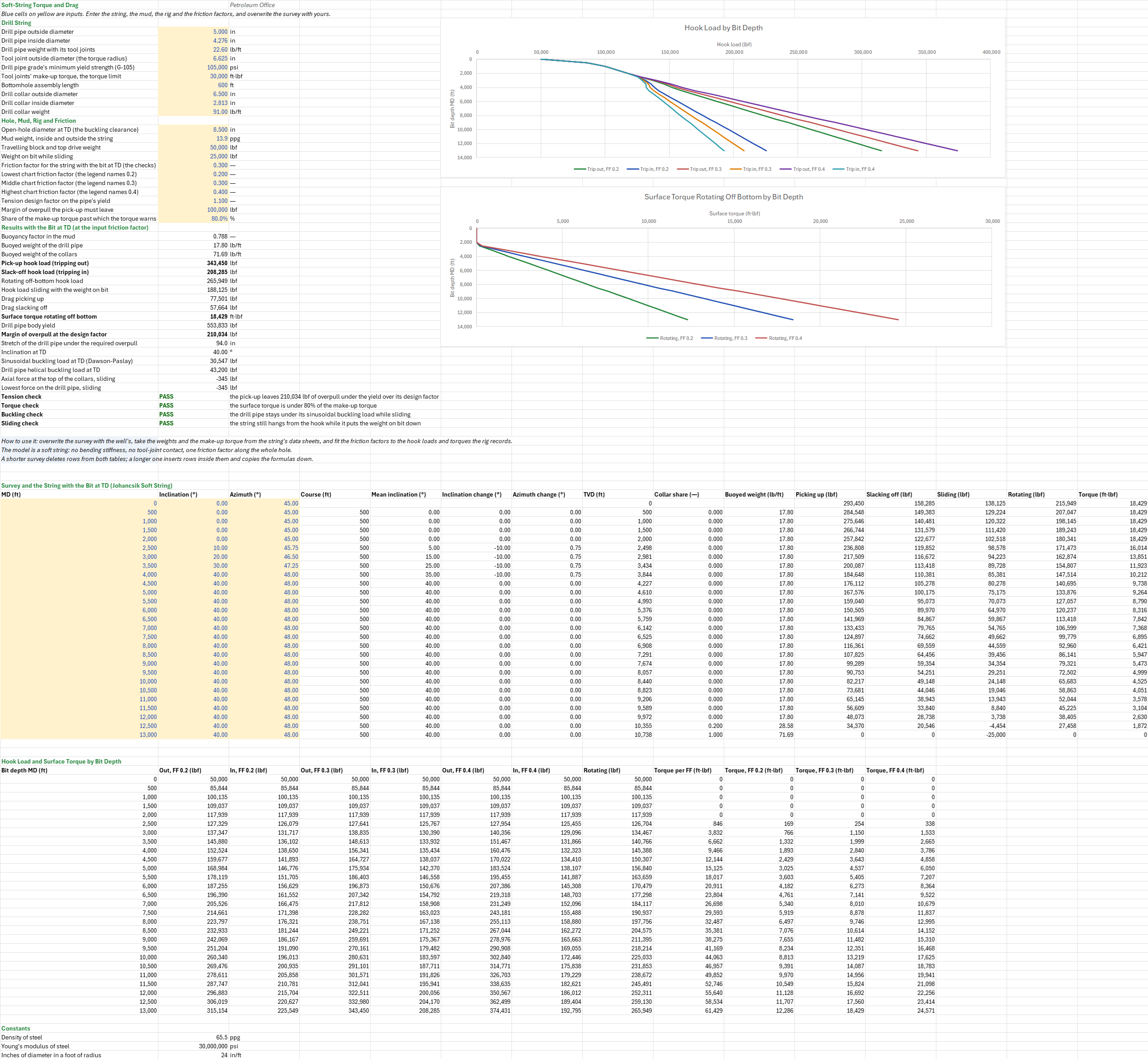
What will the hook read picking up and slacking off, how much torque does the string need to turn, and does it hold? You enter the survey, the drill pipe and collars, the hole, the mud, the rig and the friction factors. You read off the hook load picking up, slacking off, sliding and rotating, the surface torque, the overpull left under the pipe's yield, and whether the drill pipe buckles sliding, with the bit at TD and against bit depth.
Parameters:
- Drill string: the drill pipe's OD, ID and weight with its tool joints
TQ_DpOD,TQ_DpID(in),TQ_DpW(lb/ft), the tool joint ODTQ_TjOD(in), the grade's yieldTQ_Yp(psi), the make-up torqueTQ_MakeUp(ft·lbf), and the bottomhole assembly's lengthTQ_BhaL(ft) and the collars' OD, ID and weightTQ_BhaOD,TQ_BhaID(in),TQ_BhaW(lb/ft) - Hole, mud, rig and friction: the open hole
TQ_Hole(in), the mudTQ_MW(ppg), the block weightTQ_Blockand the weight on bitTQ_WOB(lbf), the design friction factorTQ_Muand the chart's threeTQ_Mu1,TQ_Mu2,TQ_Mu3, the tension design factorTQ_DFt, the margin of overpullTQ_MOP(lbf) and the share of the make-up torque past which the torque warnsTQ_TorqueWarn - Survey: measured depth, inclination and azimuth per station, in the
TQ_Surveytable
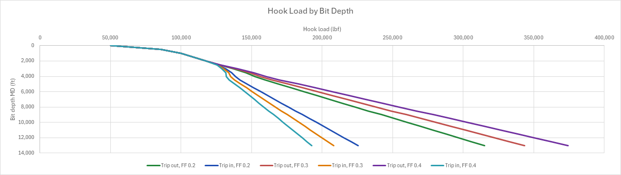
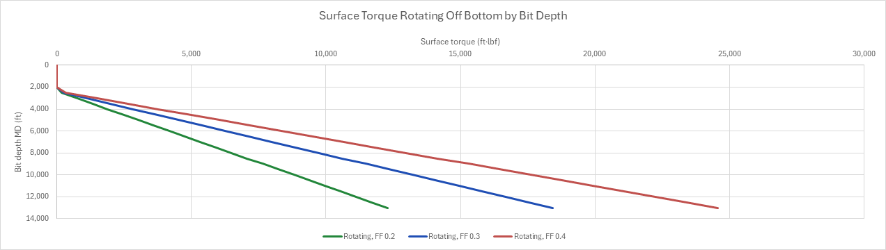
How to use it: The survey is a planned path made up for the example. Overwrite it with the well's survey; for a shorter survey delete rows from both tables, and for a longer one insert rows inside them and copy the formulas down. Take the weights, the tool joints' make-up torque and the grade from the string's data sheets, with the worn pipe's class if it is not new. The friction factors are a fit, not a property: calibrate them to the pick-up, slack-off and rotating weights and the off-bottom torque the rig records on the way in, typically 0.15 to 0.25 in casing and 0.25 to 0.4 in open hole with water-based mud. One table runs the march with the bit at TD at the design friction factor: picking up, slacking off, sliding with the weight on bit, and rotating off bottom, with the torque the rotation builds. A second runs it again with the bit at every station and at three friction factors, and charts the hook load tripping out and in and the surface torque against bit depth. Check that the pick-up leaves the required margin of overpull under the pipe's yield over its design factor, that the surface torque stays under a share of the tool joints' make-up torque (80 % by default) and under the make-up torque itself, that the drill pipe's lowest axial force sliding stays under the sinusoidal buckling load and well clear of the helical one, where it can lock up, and that the string can put the weight on bit down while it still hangs from the hook. The drill pipe's stretch under the required overpull is shown beside the checks.
Method: Johancsik's soft-string model treats each course between two stations as an element of string lying on the wall. Each course from station i − 1 to station i has a length ΔL, a mean inclination θ, an inclination change Δθ (upper less lower) and an azimuth change Δα, and a buoyed weight w per foot, the drill pipe's or the collars' as the collars fill the bottom of the string (BF = 1 − ρm/ρs with the same mud inside and out). With F the axial force at the course's foot, the normal force is N = √((F Δα sin θ)² + (F Δθ + w ΔL sin θ)²) and the force at its top is F + w ΔL cos θ ± μ N, + picking up and − slacking off (Johancsik, Friesen and Dawson, 1984). Rotating, no axial friction acts, the force at the top is F + w ΔL cos θ, and the course adds μ N r to the torque at the tool joints, with r the tool joints' (or the collars') radius. The march starts at the bit with 0 for the trips and rotating and minus the weight on bit sliding, and the hook load is the force at surface plus the block weight. With the bit at a shallower station the march starts there with the collars above it, so each row of the bit-depth table runs the march again over the courses from the bit up, reading each course's length and angles from the survey table. Rotating, the force at a course's foot is the buoyed weight below it, so the torque sums each course's moment straight from the vertical depths, and the surface torque at each friction factor is that sum times the factor. The vertical depth is the courses' ΔL cos θ added up. The buckling loads are Dawson and Paslay's for the drill pipe at TD's inclination and √2 times it for the helix, and the force at the collars' top sliding is the weight on bit plus their buoyed weight's axial part less its drag, the collars being straight at the bit's inclination.
Example: The drilling family's reference well, the one the pore-pressure, casing-design, cement and surge sheets use, drilled as a directional well, since a vertical hole has no drag: the same casing points by measured depth along a build-and-hold path, vertical to a 2,000 ft kick-off, built at 2°/100 ft to 40° at 4,000 ft while it turns from 45° to 48° azimuth, and held to TD at 13,000 ft (10,738 ft TVD), with a station every 500 ft. The bit is on bottom in the 8½-in. production hole, in the 13.9 ppg mud. The string is 5-in. 19.5 lb/ft G-105 drill pipe (ID 4.276 in., 22.6 lb/ft with its NC50 tool joints of 6⅝ in., yield 105,000 psi, make-up torque 30,000 ft·lbf) over 600 ft of 6½-in. collars (ID 2-13/16 in., 91 lb/ft). The block and top drive weigh 50,000 lbf, the slide puts 25,000 lbf on the bit, the design friction factor is 0.3 and the chart's are 0.2, 0.3 and 0.4. The pick-up has to leave 100,000 lbf of overpull under the yield over a design factor of 1.1.
In 13.9 ppg mud the buoyancy factor is 0.7878, so the drill pipe weighs 17.80 lb/ft and the collars 71.69 lb/ft. With the bit at TD and a friction factor of 0.3 the hook reads 343,450 lbf picking up, 208,285 lbf slacking off and 265,949 lbf rotating off bottom, so the drag is 77,501 lbf out and 57,664 lbf in. Sliding with 25,000 lbf on the bit it reads 188,125 lbf. Rotating off bottom takes 18,429 ft·lbf at surface, 61 % of the 30,000 ft·lbf make-up torque. The pipe body yields at 553,833 lbf, 503,485 lbf over the 1.1 design factor, which leaves 210,034 lbf of overpull, over the 100,000 lbf required. The drill pipe stretches 94.0 in. under that 100,000 lbf. Sliding, the collars take nearly all of the weight on bit and the drill pipe's lowest force is −345 lbf at their top, far under the 30,547 lbf sinusoidal and 43,200 lbf helical buckling loads at 40°. Against bit depth, the three friction factors spread the hook loads from 315,154 lbf out and 225,549 lbf in at 0.2 to 374,431 lbf out and 192,795 lbf in at 0.4, and the surface torque from 12,286 to 24,571 ft·lbf; at 0.4 the torque passes 80 % of the make-up torque. The 2,000 ft build adds nearly half of the torque (8,217 of the 18,429 ft·lbf at 0.3): there the string's tension pulls it into the high side of the curve.
Functions used
None: the blueprint calculates with Excel's own functions.
Names (60)
| Name | Refers to | Comment |
|---|---|---|
PO.DE.TD.BuoyancyLAMBDA |
=LAMBDA(PipeW_lbft, PipeOD_in, PipeID_in, MWi_ppg, MWo_ppg, RhoSteel_ppg, LET(bf, 1 - (MWo_ppg*PipeOD_in^2 - MWi_ppg*PipeID_in^2) / (RhoSteel_ppg*(PipeOD_in^2 - PipeID_in^2)), HSTACK(bf, PipeW_lbft*bf))) |
Buoyancy factor of a pipe with different fluids inside and outside, and its buoyed weight per foot: {BF, lb/ft}. |
PO.DE.Casing.Axial.YieldLAMBDA |
=LAMBDA(BodyOD_in, BodyWall_in, BodyYp_psi, PI()/4*(BodyOD_in^2-(BodyOD_in-2*BodyWall_in)^2)*BodyYp_psi) |
API TR 5C3 pipe-body yield strength, Fy = (pi/4)(D^2 - d^2) Yp, [lbf]. |
PO.DE.TD.StretchLAMBDA |
=LAMBDA(F_lbf, W_lbft, L_ft, OD_in, ID_in, E_psi, 12*L_ft*(F_lbf + W_lbft*L_ft/2) / (E_psi*PI()/4*(OD_in^2 - ID_in^2))) |
Hooke stretch of a pipe string, in., under an end load plus its own weight: 12 L (F + w L / 2) / (E As). |
PO.DE.TD.Buckling.SinusoidalLAMBDA |
=LAMBDA(OD_in, ID_in, Dh_in, Wb_lbft, Inc_deg, E_psi, Mode, LET(mi, PI()/64*(OD_in^4 - ID_in^4), wpi, Wb_lbft/12, IF(Mode=1, 1.94*(E_psi*mi*wpi^2)^(1/3), 2*SQRT(E_psi*mi*wpi*SIN(RADIANS(Inc_deg))/((Dh_in - OD_in)/2))))) |
Sinusoidal buckling load, lbf: Dawson-Paslay in an inclined hole (Mode 0) or Lubinski 1.94 (EI w^2)^(1/3) in a vertical one (Mode 1). |
PO.DE.TD.Buckling.HelicalLAMBDA |
=LAMBDA(OD_in, ID_in, Dh_in, Wb_lbft, Inc_deg, E_psi, Mode, LET(mi, PI()/64*(OD_in^4 - ID_in^4), wpi, Wb_lbft/12, IF(Mode=1, 5.55*(E_psi*mi*wpi^2)^(1/3), 2*SQRT(2)*SQRT(E_psi*mi*wpi*SIN(RADIANS(Inc_deg))/((Dh_in - OD_in)/2))))) |
Helical buckling load, lbf: the square root of 2 times Dawson-Paslay in an inclined hole (Mode 0) or 5.55 (EI w^2)^(1/3) in a vertical one (Mode 1). |
TQ_DpOD |
$B$4 |
Drill pipe outside diameter, in |
TQ_DpID |
$B$5 |
Drill pipe inside diameter, in |
TQ_DpW |
$B$6 |
Drill pipe weight with its tool joints, lb/ft |
TQ_TjOD |
$B$7 |
Tool joint outside diameter (the torque radius), in |
TQ_Yp |
$B$8 |
Drill pipe grade's minimum yield strength (G-105), psi |
TQ_MakeUp |
$B$9 |
Tool joints' make-up torque, the torque limit, ft·lbf |
TQ_BhaL |
$B$10 |
Bottomhole assembly length, ft |
TQ_BhaOD |
$B$11 |
Drill collar outside diameter, in |
TQ_BhaID |
$B$12 |
Drill collar inside diameter, in |
TQ_BhaW |
$B$13 |
Drill collar weight, lb/ft |
TQ_Hole |
$B$15 |
Open-hole diameter at TD (the buckling clearance), in |
TQ_MW |
$B$16 |
Mud weight, inside and outside the string, ppg |
TQ_Block |
$B$17 |
Travelling block and top drive weight, lbf |
TQ_WOB |
$B$18 |
Weight on bit while sliding, lbf |
TQ_Mu |
$B$19 |
Friction factor for the string with the bit at TD (the checks) |
TQ_Mu1 |
$B$20 |
Lowest chart friction factor (the legend names 0.2) |
TQ_Mu2 |
$B$21 |
Middle chart friction factor (the legend names 0.3) |
TQ_Mu3 |
$B$22 |
Highest chart friction factor (the legend names 0.4) |
TQ_DFt |
$B$23 |
Tension design factor on the pipe's yield |
TQ_MOP |
$B$24 |
Margin of overpull the pick-up must leave, lbf |
TQ_TorqueWarn |
$B$25 |
Share of the make-up torque past which the torque warns, % |
TQ_Inputs |
$B$4:$B$25 |
The drill pipe, its tool joints, grade and make-up torque, the collars, the hole, the mud, the block weight, the weight on bit, the friction factors, the tension design factor, the margin of overpull and the torque warning share |
TQ_BF |
$B$27 |
Buoyancy factor in the mud |
TQ_WbDp |
$B$28 |
Buoyed weight of the drill pipe, lb/ft |
TQ_WbBha |
$B$29 |
Buoyed weight of the collars, lb/ft |
TQ_PickUp |
$B$30 |
Pick-up hook load (tripping out), lbf |
TQ_SlackOff |
$B$31 |
Slack-off hook load (tripping in), lbf |
TQ_Rotating |
$B$32 |
Rotating off-bottom hook load, lbf |
TQ_Sliding |
$B$33 |
Hook load sliding with the weight on bit, lbf |
TQ_DragOut |
$B$34 |
Drag picking up, lbf |
TQ_DragIn |
$B$35 |
Drag slacking off, lbf |
TQ_Torque |
$B$36 |
Surface torque rotating off bottom, ft·lbf |
TQ_Yield |
$B$37 |
Drill pipe body yield, lbf |
TQ_Overpull |
$B$38 |
Margin of overpull at the design factor, lbf |
TQ_Stretch |
$B$39 |
Stretch of the drill pipe under the required overpull, in |
TQ_IncTD |
$B$40 |
Inclination at TD, ° |
TQ_Fsin |
$B$41 |
Sinusoidal buckling load at TD (Dawson-Paslay), lbf |
TQ_Fhel |
$B$42 |
Drill pipe helical buckling load at TD, lbf |
TQ_FBha |
$B$43 |
Axial force at the top of the collars, sliding, lbf |
TQ_Fmin |
$B$44 |
Lowest force on the drill pipe, sliding, lbf |
TQ_TensionCheck |
$B$45 |
Tension check verdict |
TQ_TensionCheckNote |
$C$45 |
Tension check comment |
TQ_TorqueCheck |
$B$46 |
Torque check verdict |
TQ_TorqueCheckNote |
$C$46 |
Torque check comment |
TQ_BucklingCheck |
$B$47 |
Buckling check verdict |
TQ_BucklingCheckNote |
$C$47 |
Buckling check comment |
TQ_SlideCheck |
$B$48 |
Sliding check verdict |
TQ_SlideCheckNote |
$C$48 |
Sliding check comment |
TQ_Results |
$B$27:$B$48 |
The buoyed weights, the hook loads with the bit at TD, the drags, the surface torque, the pipe's yield and the margin of overpull, the stretch, the buckling loads, the lowest force sliding, and the four checks |
TQ_Survey |
$A$57:$C$83 |
Survey stations: measured depth, inclination, azimuth |
TQ_March |
$D$57:$O$83 |
Each course's length, angles, vertical depth, collar share and buoyed weight, and the forces and torque with the bit at TD |
TQ_Curve |
$A$88:$L$114 |
Each bit depth's hook load tripping out and in at the three friction factors and rotating, its torque per unit friction factor, and its surface torque at the three |
TQ_Steel |
$B$117 |
Density of steel, ppg |
TQ_E |
$B$118 |
Young's modulus of steel, psi |
TQ_DiaFt |
$B$119 |
Inches of diameter in a foot of radius, in/ft |
Details
| Inserts | 119 rows × 15 columns |
| Category | Drilling Engineering |
| For agents and tools | Descriptor (.md) |