Injector Hall Plot and Voidage Replacement
Description
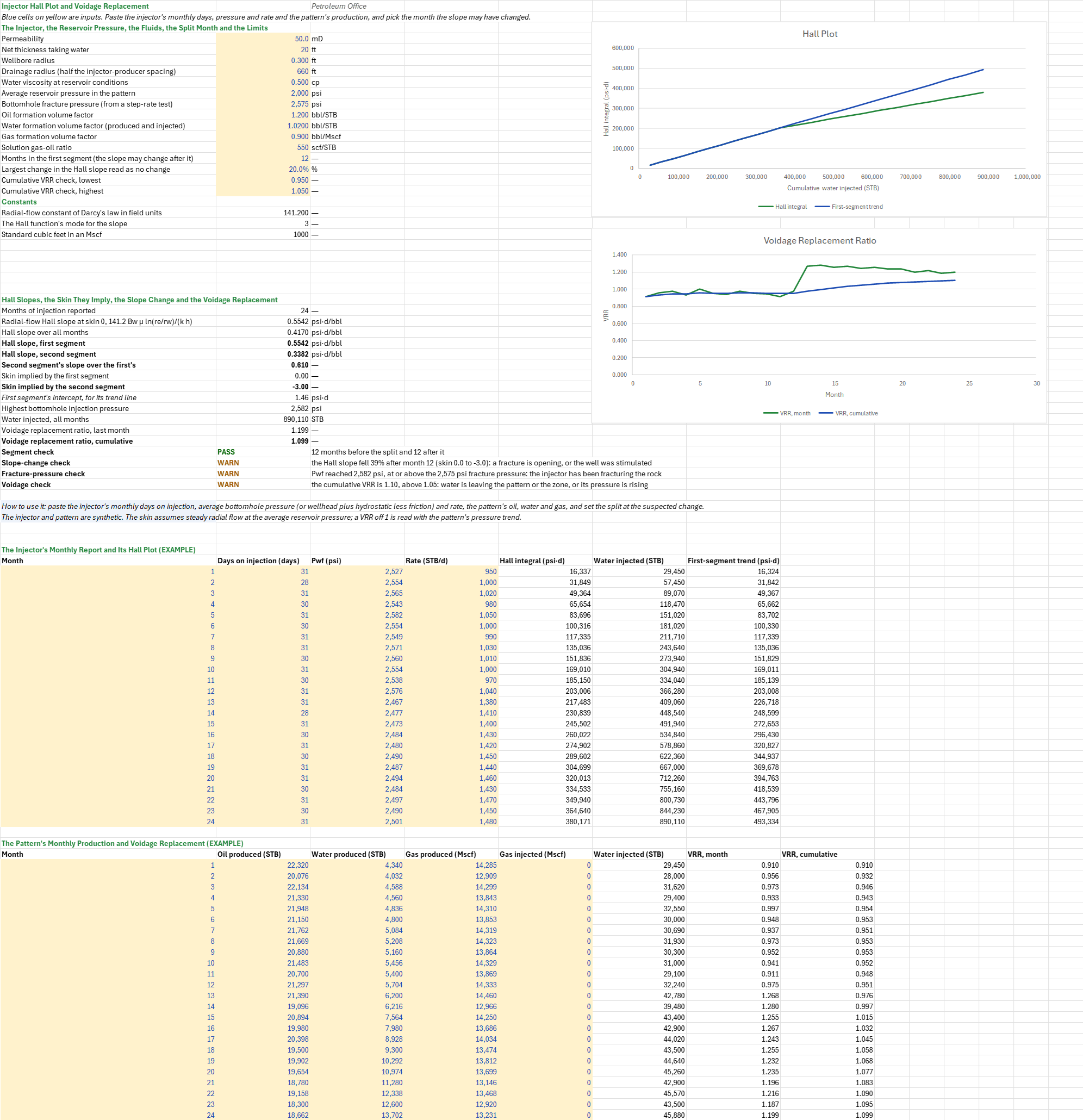
Is the injector still taking water as it did, and is the pattern getting back what it gives up? You paste the injector's monthly days on injection, bottomhole pressure and rate, the pattern's monthly oil, water and gas, and the month after which the slope may have changed. You read off the Hall slope before and after that month, the skin each slope implies, a flag for plugging or a fracture opening, and the pattern's voidage replacement ratio (VRR), month by month and cumulative.
Parameters:
- Injector: the permeability
HALL_K(mD), the net thickness taking waterHALL_H(ft), the wellbore radiusHALL_Rwand the drainage radiusHALL_Re(ft), and the water viscosityHALL_Muw(cp) - Pressures: the average reservoir pressure
HALL_Peand the bottomhole fracture pressureHALL_Pfrac(psi) - Fluids:
HALL_BoandHALL_Bw(bbl/STB),HALL_Bg(bbl/Mscf) and the solution GORHALL_Rs(scf/STB) - Split: the months in the first segment,
HALL_Split - Limits:
HALL_SlopeTolfor the slope change, andHALL_VrrLoandHALL_VrrHifor the cumulative VRR - Injection: each month's days on injection, average bottomhole pressure and average rate, in the injection table (
HALL_dt,HALL_Pwf,HALL_Q) - Production: each month's oil and water (STB) and gas (Mscf) produced, and any gas injected, in the production table
How to use it: The injector and pattern are synthetic. Paste the injector's monthly days on injection, average bottomhole pressure and rate, over the injection table's rows; a wellhead pressure plus the hydrostatic head less the tubing friction stands in for a bottomhole one. Set the reservoir pressure from the latest survey, and the split at the month you suspect a change, from the plot's bend or a workover date. Paste the pattern's allocated oil, water and gas, and any gas injected, over the production table.
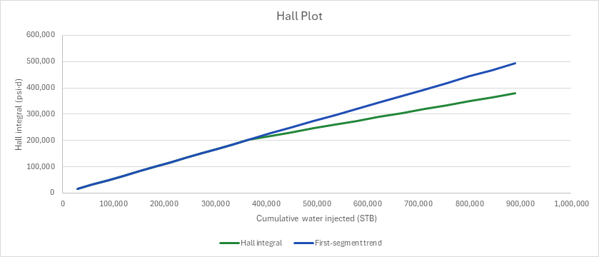
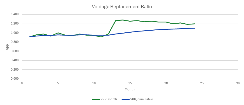
The Hall plot draws the Hall integral, the sum of (pwf − pe) Δt, against the cumulative water injected, with the first segment's line carried across the whole history so that a bend shows. A second chart draws the monthly and cumulative VRR. The ratio of the two segments' slopes flags plugging, when the slope rises, or a fracture opening, when it falls.
Four checks give PASS, WARN or FAIL. The segment check fails when the split leaves either segment under two months. The slope-change check warns when the second segment's slope differs from the first's by more than the limit, naming plugging or fracturing. The fracture-pressure check warns when the highest bottomhole pressure reaches the fracture pressure. The voidage check warns when the cumulative VRR is outside its band.
Method: In each month the Hall integral grows by (pwf − pe) Δt and the cumulative injection by q Δt. Each segment's slope is the least-squares slope of the integral against the cumulative injection over its rows; a running sum restarted at the segment has the same slope. Under steady radial flow the slope is 141.2 Bw μw (ln(re/rw) + s)/(k h), so the skin a slope implies is s = slope · k h/(141.2 Bw μw) − ln(re/rw). The slope ratio is the second segment's over the first's.
VRR = (Wi Bw + Gi Bg)/(Np Bo + (Gp − Np Rs) Bg + Wp Bw), each period's, and the cumulative ratio divides the running sums. The gas volumes are in Mscf, so Rs enters in Mscf/STB.
Example: The default case is a synthetic injector in a 50 mD sand, 20 ft taking water, with a 0.3 ft wellbore and a 660 ft drainage radius, injecting 0.50 cp water at Bw 1.02 into a pattern held at 2,000 psi. Its first year's pressures follow the radial-flow Hall slope at skin 0, about 1,000 STB/d at 2,530 to 2,580 psi. In the second year the slope is that of skin −3, as a fracture opening leaves it: about 1,450 STB/d at 2,470 to 2,500 psi. A step-rate test put the fracture pressure at 2,575 psi. The pattern's producers make about 700 STB/d of oil, falling, with water rising from 140 to 440 STB/d and a GOR near 650 scf/STB against an Rs of 550; Bo is 1.20 and Bg 0.90 bbl/Mscf.
The radial-flow slope at skin 0 is 0.5542 psi·d/bbl. Over the first twelve months the Hall slope is 0.5542, skin 0.0; over the second twelve it is 0.3382, skin −3.0. It fell 39% after month 12, and the slope-change check warns of a fracture opening. Pwf reached 2,582 psi in month 5, above the 2,575 psi fracture pressure, and that check warns too: the injector was near fracturing from the start. Over all 24 months the slope is 0.4170. The injector put away 890,110 STB. The VRR held near 0.95 in the first year and rose to 1.2 to 1.3 in the second, as the fractured well took more water; the cumulative VRR is 1.10, above the band, and warns that water is leaving the pattern or the zone. With the split at month 18 the first segment mixes both years, its slope falls to 0.4709 and its skin to −1.16, and the change reads 28%: set the split at the bend.
Functions used
None: the blueprint calculates with Excel's own functions.
Names (48)
| Name | Refers to | Comment |
|---|---|---|
PO.RES.Waterflood.HallLAMBDA |
=LAMBDA(dt, Pwf, Pe, Q, Mode, LET(hall, SCAN(0, (Pwf-Pe)*dt, LAMBDA(acc, v, acc+v)), wi, SCAN(0, Q*dt, LAMBDA(acc, v, acc+v)), IF(Mode=1, hall, IF(Mode=2, wi, IF(Mode=3, SLOPE(hall, wi), NA()))))) |
Hall plot of an injector: Mode 1 Hall integral, psi-d; 2 cumulative injection, bbl; 3 Hall slope, psi-d/bbl, by least squares |
PO.RES.Waterflood.VRRLAMBDA |
=LAMBDA(Np, Wp, Gp, Bo, Bw, Bg, Rs, Wi, Gi, Mode, LET(inj, Wi*Bw+Gi*Bg, wd, Np*Bo+(Gp-Np*Rs)*Bg+Wp*Bw, IF(Mode=1, inj/wd, IF(Mode=2, SCAN(0, inj, LAMBDA(acc, v, acc+v))/SCAN(0, wd, LAMBDA(acc, v, acc+v)), NA())))) |
Voidage replacement ratio in reservoir barrels, injected over withdrawn: Mode 1 per period, 2 cumulative |
HALL_K |
$B$4 |
Permeability, mD |
HALL_H |
$B$5 |
Net thickness taking water, ft |
HALL_Rw |
$B$6 |
Wellbore radius, ft |
HALL_Re |
$B$7 |
Drainage radius (half the injector-producer spacing), ft |
HALL_Muw |
$B$8 |
Water viscosity at reservoir conditions, cp |
HALL_Pe |
$B$9 |
Average reservoir pressure in the pattern, psi |
HALL_Pfrac |
$B$10 |
Bottomhole fracture pressure (from a step-rate test), psi |
HALL_Bo |
$B$11 |
Oil formation volume factor, bbl/STB |
HALL_Bw |
$B$12 |
Water formation volume factor (produced and injected), bbl/STB |
HALL_Bg |
$B$13 |
Gas formation volume factor, bbl/Mscf |
HALL_Rs |
$B$14 |
Solution gas-oil ratio, scf/STB |
HALL_Split |
$B$15 |
Months in the first segment (the slope may change after it) |
HALL_SlopeTol |
$B$16 |
Largest change in the Hall slope read as no change, % |
HALL_VrrLo |
$B$17 |
Cumulative VRR check, lowest |
HALL_VrrHi |
$B$18 |
Cumulative VRR check, highest |
HALL_Inputs |
$B$4:$B$18 |
The injector's k, h, rw and re, the water viscosity, the reservoir and fracture pressures, Bo, Bw, Bg and Rs, the split month and the check limits |
HALL_Darcy |
$B$20 |
Radial-flow constant of Darcy's law in field units |
HALL_ModeSlope |
$B$21 |
The Hall function's mode for the slope |
HALL_ScfPerMscf |
$B$22 |
Standard cubic feet in an Mscf |
HALL_N |
$B$29 |
Months of injection reported |
HALL_Ideal |
$B$30 |
Radial-flow Hall slope at skin 0, 141.2 Bw μ ln(re/rw)/(k h), psi·d/bbl |
HALL_SlopeAll |
$B$31 |
Hall slope over all months, psi·d/bbl |
HALL_SlopeEarly |
$B$32 |
Hall slope, first segment, psi·d/bbl |
HALL_SlopeLate |
$B$33 |
Hall slope, second segment, psi·d/bbl |
HALL_Ratio |
$B$34 |
Second segment's slope over the first's |
HALL_SkinEarly |
$B$35 |
Skin implied by the first segment |
HALL_SkinLate |
$B$36 |
Skin implied by the second segment |
HALL_Icpt |
$B$37 |
First segment's intercept, for its trend line, psi·d |
HALL_PwfMax |
$B$38 |
Highest bottomhole injection pressure, psi |
HALL_Wi |
$B$39 |
Water injected, all months, STB |
HALL_VrrLast |
$B$40 |
Voidage replacement ratio, last month |
HALL_VrrCum |
$B$41 |
Voidage replacement ratio, cumulative |
HALL_SplitCheck |
$B$42 |
Segment check verdict |
HALL_SplitCheckNote |
$C$42 |
Segment check comment |
HALL_SlopeCheck |
$B$43 |
Slope-change check verdict |
HALL_SlopeCheckNote |
$C$43 |
Slope-change check comment |
HALL_FracCheck |
$B$44 |
Fracture-pressure check verdict |
HALL_FracCheckNote |
$C$44 |
Fracture-pressure check comment |
HALL_VrrCheck |
$B$45 |
Voidage check verdict |
HALL_VrrCheckNote |
$C$45 |
Voidage check comment |
HALL_Results |
$B$29:$B$45 |
The months, the radial-flow slope, the Hall slope over all months and each segment, their ratio and skins, the highest Pwf, the water injected, the VRR and four checks |
HALL_Curve |
$A$53:$G$76 |
Each month's days, bottomhole pressure and rate, the Hall integral, the cumulative injection and the first segment's trend |
HALL_dt |
$B$53:$B$76 |
Days on injection in each month |
HALL_Pwf |
$C$53:$C$76 |
Average bottomhole injection pressure in each month, psi |
HALL_Q |
$D$53:$D$76 |
Average injection rate in each month, STB/d |
HALL_VrrCurve |
$A$80:$H$103 |
Each month's oil, water and gas produced, gas and water injected, and the monthly and cumulative VRR |
Details
| Inserts | 103 rows × 8 columns |
| Category | Reservoir Engineering |
| For agents and tools | Descriptor (.md) |