Gas-Lift Unloading Design
Description
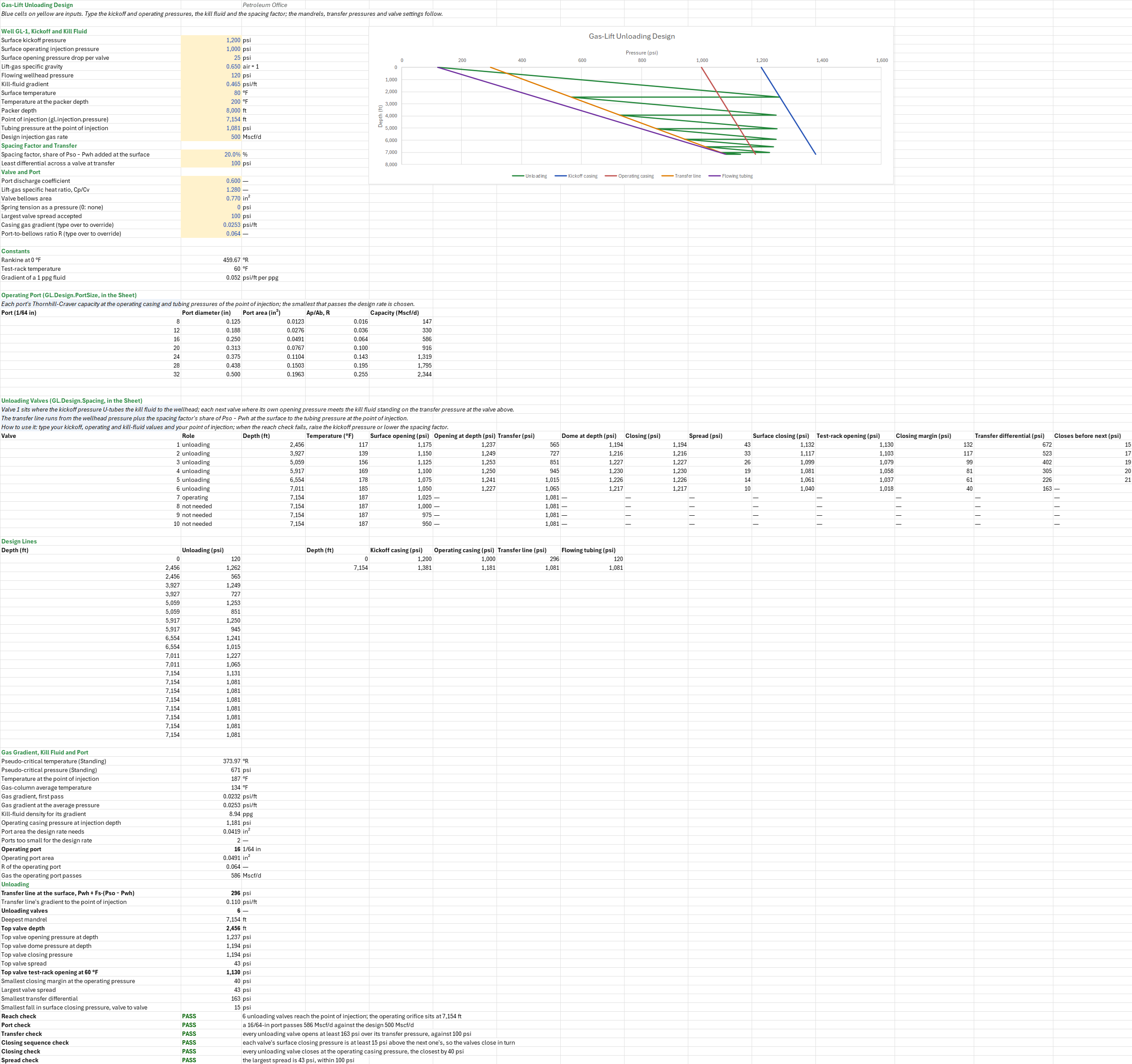
Where do the unloading valves of a continuous gas-lift well go, and what does each one see as the well unloads its kill fluid? You enter the kickoff and operating injection pressures, the well and its kill fluid, the point of injection, a spacing factor and the valve's port and bellows. You read off each injection-pressure-operated (IPO) valve's depth, the transfer pressure there, its dome and test-rack setting, its closing pressure and spread, and the operating port.
Parameters:
- Pressures: surface kickoff and operating injection pressures and the drop per valve (
GLU_Pko,GLU_Pso,GLU_Drop) - Well: lift-gas gravity, wellhead pressure, kill-fluid gradient, surface and packer temperatures and the packer depth (
GLU_SG,GLU_Pwh,GLU_Gs,GLU_Ts,GLU_Tb,GLU_Dpk) - From the injection-pressure sheet: the point of injection, the tubing pressure there and the design gas rate (
GLU_Dpoi,GLU_Ptpoi,GLU_Qgi) - Spacing: the spacing factor (
GLU_Fs, 20 %) and the least differential across a valve at transfer (GLU_dPmin, 100 psi) - Port and valve: discharge coefficient, specific heat ratio, bellows area and spring tension (
GLU_Cd,GLU_k,GLU_Ab,GLU_St) and the largest spread accepted (GLU_SpreadMax) - Overrides: the casing gas gradient and R, each computed in the sheet until a measured value is typed over it (
GLU_Gg,GLU_R)
How to use it: Type your kickoff and operating pressures, the kill fluid's gradient (0.052 psi/ft per ppg) and the point of injection and tubing pressure from your own Gas-Lift Injection Pressure and Point of Injection sheet. Type your valve's bellows area and port sizes from its catalogue. The spacing factor is a design choice: a larger one draws the transfer line nearer the casing, which spaces the valves closer and gives more of them, with a smaller differential at each. The table has ten mandrels; if the reach check fails, raise the kickoff pressure, lower the spacing factor or the drop per valve, or extend the table's formulas by a row per mandrel.
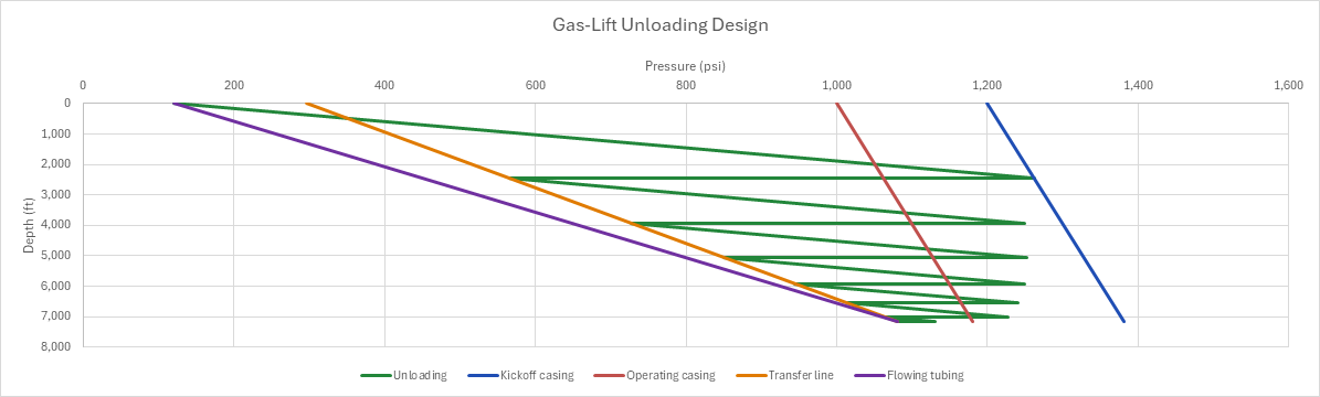
For each unloading valve the sheet gives its depth and temperature, its opening pressure at the surface and at depth, the transfer pressure there, the nitrogen dome it needs, and its closing pressure at depth and at the surface. It also gives the spread, the test-rack opening pressure at 60 °F, its closing margin at the operating pressure, the differential at transfer, and how far its surface closing pressure sits above the next valve's. The pressure-depth design chart draws the kickoff and operating casing lines, the transfer line, the flowing tubing line and the unloading zig-zag.
Method: The kickoff pressure U-tubes the kill fluid to the wellhead, which places the top valve. Each next mandrel sits where the kill fluid, standing on the transfer pressure at the valve above, meets that valve's own opening pressure. The transfer pressures lie on a design line drawn with a spacing factor: the wellhead pressure plus a share of the casing-to-wellhead difference at the surface, straight down to the flowing tubing pressure at the point of injection. The operating port is sized in the sheet by Thornhill-Craver.
- Gas gradient. The casing gas gradient Gg is the static gas-column gradient at the column's average temperature, in two passes as the valve-setting sheet takes it: at the operating pressure, then at the average pressure that first gradient gives to the point of injection. z is Dranchuk-Abou-Kassem at Standing's pseudo-criticals.
- Kill fluid. The kill fluid's gradient Gs is an input; the sheet shows its density, Gs/0.052 ppg.
- Transfer line. At the surface it starts at Ptr,0 = Pwh + Fs·(Pso − Pwh). It runs straight to the tubing pressure at the point of injection: Ptr(D) = Ptr,0 + (Ptpoi − Ptr,0)·D/Dpoi.
- Spacing, written in the sheet. The top valve sits where the kickoff casing pressure balances the kill fluid from the wellhead, D1 = (Pko − Pwh)/(Gs − Gg). Valve i opens at the surface at Psoi = Pko − i·ΔPdrop. Each next valve sits where its casing pressure meets the kill fluid standing on the transfer pressure at the valve above: Di = Di−1 + (Psoi + Gg·Di−1 − Ptr(Di−1))/(Gs − Gg). The first mandrel at or below the point of injection takes the operating orifice; the rows after it are not needed.
- Port size, written in the sheet. The Thornhill-Craver rate is linear in the port area, so the area the design rate needs is Qgi over the throughput of a 1 in² port, taken at the operating casing and tubing pressures of the point of injection. The smallest catalogue port that passes Qgi is the operating port, and its area over the bellows area is R. The unloading valves share it.
- Settings of each unloading valve. The opening pressure at depth is Pvo = Psoi + Gg·D. The dome that opens it against the transfer pressure there is Pd = (1 − R)·(Pvo − St) + R·Ptr. It closes at Pvc = Pd + St·(1 − R), its spread is Pvo − Pvc, and its surface closing pressure is Pvc − Gg·D. The test-rack opening pressure takes the dome to 60 °F with nitrogen's z, against one atmosphere on the tubing side.
- Checks.
- Reach: a mandrel reaches the point of injection.
- Port: the operating port passes the design rate.
- Transfer: every unloading valve opens at least ΔPmin over its transfer pressure, so gas still passes as it takes over.
- Closing sequence: each valve's surface closing pressure is above the next one's, so the upper valve closes once the next takes the gas.
- Closing: every unloading valve closes at the operating casing pressure, so only the orifice injects once the well is unloaded.
- Spread: the largest spread is within the limit.
Example: The well is GL-1, the one the Gas-Lift Injection Pressure and Point of Injection, Gas-Lift Valve Setting and Gas-Lift Valve Throughput sheets use: 0.65-gravity lift gas, 120 psia at the wellhead, 80 °F at surface and 200 °F at the packer at 8,000 ft, and 500 Mscf/d of design gas. Its point of injection (7,154 ft) and the flowing tubing pressure there (1,080.5 psia) are typed in from the injection-pressure sheet. Kickoff is at 1,200 psia with a 0.465 psi/ft kill fluid, the surface opening pressure drops 25 psi per valve, and the well then operates at 1,000 psia. The spacing factor is 20 %.
The gas gradient is 0.0253 psi/ft, and the 500 Mscf/d design takes a 16/64-in port, R = 0.0638, as the valve-setting sheet finds. The kill fluid is 8.94 ppg. The transfer line starts at 120 + 0.2 × 880 = 296 psia and runs at 0.1097 psi/ft to 1,080.5 psia at the point of injection. Six unloading valves reach it, at 2,456, 3,927, 5,059, 5,917, 6,554 and 7,011 ft, and the orifice sits at 7,154 ft. The top valve, at 117 °F, opens at 1,237.1 psia against a 565.3 psia transfer pressure. Its dome holds 1,194.3 psia at depth, it closes there with a 43 psi spread, and it sets at 1,130.3 psia on the test rack. The test-rack settings fall to 1,017.6 psia at valve 6. Every valve opens at least 163 psi over its transfer pressure. The surface closing pressures fall from 1,132.2 to 1,039.6 psia, by at least 15 psi from each valve to the next. The closest valve (6) closes 40 psi above the operating casing pressure. The design reaches the point of injection, the port passes the design rate, and the valves transfer, close in turn and close at the operating pressure within the spread limit. With no spacing factor the transfer line is the valve-setting sheet's straight design tubing line, and the sheet gives that sheet's five valves, at 2,456, 4,190, 5,437, 6,319 and 6,925 ft; the 20 % factor adds a sixth. At a 1,100 psia kickoff the ten mandrels bunch up near 6,600 ft and never reach the point of injection: the reach and closing checks fail.
The sheet was checked against Guo, Lyons and Ghalambor (2007) Example Problem 13.7, whose top valve, at 2,347 ft and 126 °F with R = 0.2562 and no spring, is designed to open at 953 psia against 424 psia tubing, which needs an 817 psia dome that closes at 817 psia. To check it, put the sheet's top valve there, as on the valve-setting sheet: no spacing factor, R typed over as 0.2562, a zero gas gradient and drop, a 953 psia kickoff, a flat 424 psia tubing line, both temperatures at 126 °F, and the kill-fluid gradient that puts valve 1 at 2,347 ft (529/2,347 = 0.225394 psi/ft). The sheet returns the printed 817 psia dome and closing pressure and the 135 psi spread.
Functions used
PO.GL.Valve.ThornhillCraver(Cd, Ap, P1, P2, SG, T, [k])
Calculates gas throughput using Thornhill-Craver equation, [mscf/d].
PO.GL.Valve.Pd.Required(Pvo, R, Pt, [St])
Calculates the dome pressure at depth a valve needs to open at a given casing pressure, Pd = (1 − R)·(Pvo − S_t) + R·Pt (Guo Eq. 13.42 solved for Pd), [psi].
PO.GL.Valve.Pvc(Pd, R, [St])
Calculates valve closing pressure, Pd + S_t·(1 − R) (Guo Eq. 13.43); the dome pressure for a valve without a spring, [psi].
PO.GL.Valve.Spread(Pvo, Pvc)
Calculates valve spread (opening minus closing pressure), [psi].
PO.GL.Valve.TRO(Pd, Td, R, [St])
Calculates test rack opening pressure at 60°F, absolute, with atmospheric pressure on the tubing side, [psi]. A spring adds its tension S_t.
PO.PVT.Tpc.ByStanding(SG_gas)
Calculates pseudo-critical temperature of hydrocarbon gas using Standing correlation, [degR].
PO.PVT.Ppc.ByStanding(SG_gas)
Calculates pseudo-critical pressure of hydrocarbon gas using Standing correlation, [psi].
PO.GL.Inj.Grad(SG, P, T, Z)
Calculates gas gradient in the annulus, [psi/ft].
PO.PVT.Z.ByDAK(Ppr, Tpr)
Calculates gas compressibility factor (Z) using Dranchuk and Abou-Kassem (1975) equation of state, [dimensionless].
Names (99)
| Name | Refers to | Comment |
|---|---|---|
GLU_Pko |
$B$5 |
Surface kickoff pressure, psi |
GLU_Pso |
$B$6 |
Surface operating injection pressure, psi |
GLU_Drop |
$B$7 |
Surface opening pressure drop per valve, psi |
GLU_SG |
$B$8 |
Lift-gas specific gravity, air = 1 |
GLU_Pwh |
$B$9 |
Flowing wellhead pressure, psi |
GLU_Gs |
$B$10 |
Kill-fluid gradient, psi/ft |
GLU_Ts |
$B$11 |
Surface temperature, °F |
GLU_Tb |
$B$12 |
Temperature at the packer depth, °F |
GLU_Dpk |
$B$13 |
Packer depth, ft |
GLU_Dpoi |
$B$14 |
Point of injection (gl.injection.pressure), ft |
GLU_Ptpoi |
$B$15 |
Tubing pressure at the point of injection, psi |
GLU_Qgi |
$B$16 |
Design injection gas rate, Mscf/d |
GLU_Fs |
$B$18 |
Spacing factor, share of Pso − Pwh added at the surface, % |
GLU_dPmin |
$B$19 |
Least differential across a valve at transfer, psi |
GLU_Cd |
$B$21 |
Port discharge coefficient |
GLU_k |
$B$22 |
Lift-gas specific heat ratio, Cp/Cv |
GLU_Ab |
$B$23 |
Valve bellows area, in² |
GLU_St |
$B$24 |
Spring tension as a pressure (0: none), psi |
GLU_SpreadMax |
$B$25 |
Largest valve spread accepted, psi |
GLU_Gg |
$B$26 |
Casing gas gradient (type over to override), psi/ft |
GLU_R |
$B$27 |
Port-to-bellows ratio R (type over to override) |
GLU_Inputs |
$B$5:$B$27 |
Kickoff and operating pressures, the drop per valve, gas, wellhead, kill fluid, temperatures, depths and the design gas rate, the spacing factor and transfer differential, the port and valve, and the gas gradient and R |
GLU_R0 |
$B$30 |
Rankine at 0 °F, °R |
GLU_Track |
$B$31 |
Test-rack temperature, °F |
GLU_PsiPpg |
$B$32 |
Gradient of a 1 ppg fluid, psi/ft per ppg |
GLU_Ports |
$A$37:$E$43 |
Port sizes, diameter, area, R and Thornhill-Craver capacity at the point of injection |
GLU_Dv1 |
$C$51 |
Depth of valve 1, ft |
GLU_Ptr1 |
$G$51 |
Transfer pressure at valve 1, psia |
GLU_Tro1 |
$L$51 |
Test-rack opening pressure of valve 1 at 60 °F, psia |
GLU_Dv2 |
$C$52 |
Depth of valve 2, ft |
GLU_Ptr2 |
$G$52 |
Transfer pressure at valve 2, psia |
GLU_Tro2 |
$L$52 |
Test-rack opening pressure of valve 2 at 60 °F, psia |
GLU_Dv3 |
$C$53 |
Depth of valve 3, ft |
GLU_Ptr3 |
$G$53 |
Transfer pressure at valve 3, psia |
GLU_Tro3 |
$L$53 |
Test-rack opening pressure of valve 3 at 60 °F, psia |
GLU_Dv4 |
$C$54 |
Depth of valve 4, ft |
GLU_Ptr4 |
$G$54 |
Transfer pressure at valve 4, psia |
GLU_Tro4 |
$L$54 |
Test-rack opening pressure of valve 4 at 60 °F, psia |
GLU_Dv5 |
$C$55 |
Depth of valve 5, ft |
GLU_Ptr5 |
$G$55 |
Transfer pressure at valve 5, psia |
GLU_Tro5 |
$L$55 |
Test-rack opening pressure of valve 5 at 60 °F, psia |
GLU_Dv6 |
$C$56 |
Depth of valve 6, ft |
GLU_Ptr6 |
$G$56 |
Transfer pressure at valve 6, psia |
GLU_Tro6 |
$L$56 |
Test-rack opening pressure of valve 6 at 60 °F, psia |
GLU_Dv7 |
$C$57 |
Depth of valve 7, ft |
GLU_Ptr7 |
$G$57 |
Transfer pressure at valve 7, psia |
GLU_Tro7 |
$L$57 |
Test-rack opening pressure of valve 7 at 60 °F, psia |
GLU_Dv8 |
$C$58 |
Depth of valve 8, ft |
GLU_Ptr8 |
$G$58 |
Transfer pressure at valve 8, psia |
GLU_Tro8 |
$L$58 |
Test-rack opening pressure of valve 8 at 60 °F, psia |
GLU_Dv9 |
$C$59 |
Depth of valve 9, ft |
GLU_Ptr9 |
$G$59 |
Transfer pressure at valve 9, psia |
GLU_Tro9 |
$L$59 |
Test-rack opening pressure of valve 9 at 60 °F, psia |
GLU_Dv10 |
$C$60 |
Depth of valve 10, ft |
GLU_Ptr10 |
$G$60 |
Transfer pressure at valve 10, psia |
GLU_Tro10 |
$L$60 |
Test-rack opening pressure of valve 10 at 60 °F, psia |
GLU_Valves |
$A$51:$O$60 |
Valve schedule: role, depth, temperature, opening at surface and depth, transfer pressure, dome, closing, spread, surface closing, test-rack opening, closing margin, transfer differential and the fall to the next valve's closing pressure |
GLU_Tpc |
$B$87 |
Pseudo-critical temperature (Standing), °R |
GLU_Ppc |
$B$88 |
Pseudo-critical pressure (Standing), psi |
GLU_TPOI |
$B$89 |
Temperature at the point of injection, °F |
GLU_Tcol |
$B$90 |
Gas-column average temperature, °F |
GLU_G1 |
$B$91 |
Gas gradient, first pass, psi/ft |
GLU_GgCalc |
$B$92 |
Gas gradient at the average pressure, psi/ft |
GLU_KillPpg |
$B$93 |
Kill-fluid density for its gradient, ppg |
GLU_P1op |
$B$94 |
Operating casing pressure at injection depth, psi |
GLU_ApReq |
$B$95 |
Port area the design rate needs, in² |
GLU_Small |
$B$96 |
Ports too small for the design rate |
GLU_Port |
$B$97 |
Operating port |
GLU_Ap |
$B$98 |
Operating port area, in² |
GLU_Rport |
$B$99 |
R of the operating port |
GLU_Qport |
$B$100 |
Gas the operating port passes, Mscf/d |
GLU_Ptr0 |
$B$102 |
Transfer line at the surface, Pwh + Fs·(Pso − Pwh), psi |
GLU_Gtr |
$B$103 |
Transfer line's gradient to the point of injection, psi/ft |
GLU_Nu |
$B$104 |
Unloading valves |
GLU_Dlast |
$B$105 |
Deepest mandrel, ft |
GLU_D1 |
$B$106 |
Top valve depth, ft |
GLU_Pvo1 |
$B$107 |
Top valve opening pressure at depth, psi |
GLU_Pd1 |
$B$108 |
Top valve dome pressure at depth, psi |
GLU_Pvc1 |
$B$109 |
Top valve closing pressure, psi |
GLU_Spread1 |
$B$110 |
Top valve spread, psi |
GLU_Ptro1 |
$B$111 |
Top valve test-rack opening at 60 °F, psi |
GLU_Margin |
$B$112 |
Smallest closing margin at the operating pressure, psi |
GLU_SpreadTop |
$B$113 |
Largest valve spread, psi |
GLU_DiffMin |
$B$114 |
Smallest transfer differential, psi |
GLU_FallMin |
$B$115 |
Smallest fall in surface closing pressure, valve to valve, psi |
GLU_ReachCheck |
$B$116 |
Reach check verdict |
GLU_ReachCheckNote |
$C$116 |
Reach check comment |
GLU_PortCheck |
$B$117 |
Port check verdict |
GLU_PortCheckNote |
$C$117 |
Port check comment |
GLU_TransferCheck |
$B$118 |
Transfer check verdict |
GLU_TransferCheckNote |
$C$118 |
Transfer check comment |
GLU_SequenceCheck |
$B$119 |
Closing sequence check verdict |
GLU_SequenceCheckNote |
$C$119 |
Closing sequence check comment |
GLU_ClosingCheck |
$B$120 |
Closing check verdict |
GLU_ClosingCheckNote |
$C$120 |
Closing check comment |
GLU_SpreadCheck |
$B$121 |
Spread check verdict |
GLU_SpreadCheckNote |
$C$121 |
Spread check comment |
GLU_Results |
$B$87:$B$121 |
Pseudo-criticals, gas gradient, kill-fluid density, operating port, the transfer line, the valve count and the top valve's settings, and the reach, port, transfer, closing-sequence, closing and spread checks |
GLU_Curve |
$A$64:$H$84 |
Gas-Lift Unloading Design |
Details
| Inserts | 121 rows × 15 columns |
| Category | Gas Lift |
| For agents and tools | Descriptor (.md) |