Gas-Lift Allocation Across Four Wells by Equal Slope
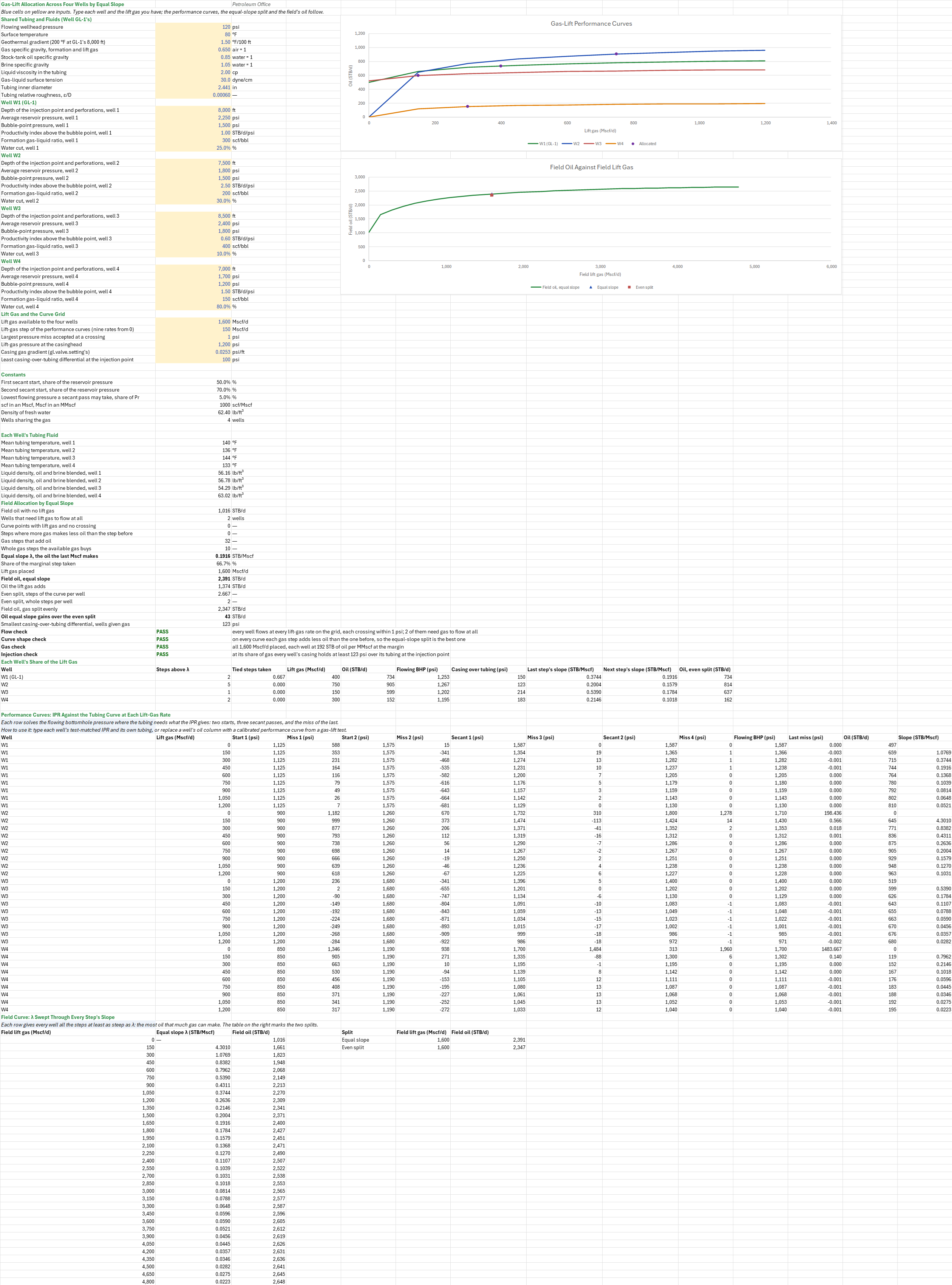
Description
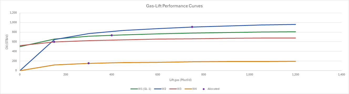
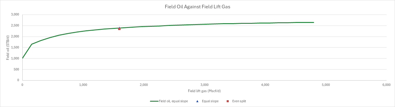
The compressor delivers less lift gas than four wells could use. How much should each well get to make the most oil? You enter the shared tubing and fluids, each well's depth, IPR, formation GLR and water cut, and the lift gas available. You read off each well's gas-lift performance curve, the equal-slope split with each well's gas, oil and flowing pressure, the oil one more Mscf makes at the margin, and the field's oil against an even split.
Parameters:
- Shared tubing and fluids: wellhead pressure, surface temperature and geothermal gradient, gas, oil and brine gravities, liquid viscosity, surface tension, tubing ID and roughness (
GLA_Pwh,GLA_Ts,GLA_Tgrad,GLA_SGg,GLA_SGo,GLA_SGw,GLA_UL,GLA_IFT,GLA_ID,GLA_Rough) - Each well n = 1 to 4: the depth of its injection point and perforations, reservoir and bubble-point pressures, productivity index, formation GLR and water cut (
GLA_Dn,GLA_Prn,GLA_Pbn,GLA_Jn,GLA_GLRn,GLA_WCn) - Lift gas and grid: the gas available, the curve's gas step and the crossing tolerance (
GLA_Gav,GLA_Step,GLA_Tol) - Injection check: the casinghead lift-gas pressure, the casing gas gradient (the Gas-Lift Valve Setting sheet's 0.0253 psi/ft) and the least casing-over-tubing differential (
GLA_Pinj,GLA_Gg,GLA_dPmin)
How to use it: Type each well's test-matched IPR and its own depth, GLR and water cut, and the gas the compressor can spare. The four wells share one tubing and one set of fluids; for wells that differ, put each well's own ID or temperature into its rows' formulas. A gas-lift test that measures oil at several injection rates is a better performance curve than any model: type its oil over a well's oil column. Check that every curve point finds its crossing, that every curve bends over, that the wells can use all the gas, and that every well keeps its injection margin. The wells W2 to W4 and W1's IPR are synthetic.
Method: The sheet builds each well's gas-lift performance curve, oil against lift gas, at nine injection rates. At each rate the operating point is the crossing of the well's composite Vogel IPR with its Hagedorn-Brown tubing curve, which carries the formation gas plus the lift gas. The crossing is solved in the sheet by the secant method on the flowing bottomhole pressure: two starts and three passes, in columns, 180 tubing calls in all. The available gas is then shared by equal slope. Each step of gas goes to the well where it adds the most oil, until the gas runs out, so every well ends where one more Mscf makes the same oil, λ. A sweep of λ through every step's slope gives the field's own performance curve, with the equal-slope split and an even split marked on it.
- Tubing fluid. Each well's liquid is its oil and brine blended by its water cut, ρL = (γo·(1 − WC) + γw·WC)·62.4 lb/ft³. The tubing's mean temperature is the surface's plus half the geothermal rise to the well's depth.
- Operating point at one injection rate. At a trial flowing pressure pwf, the IPR gives the liquid rate q (composite Vogel: straight-line above Pb, Vogel below). The tubing then needs pin(q) from the wellhead at q and a gas rate of (GLRf·q/1,000 + Qgi)/1,000 MMscf/d. The operating point is where the miss pin(q(pwf)) − pwf is zero. The sheet starts at 50 % and 70 % of Pr and takes three secant passes, each clamped between 5 % of Pr and Pr (the IPR function throws above Pr). The last pass's miss must be within 1 psi; otherwise the point counts as not flowing and its oil as zero. The oil is q·(1 − WC).
- Equal slope, written in the sheet. The slope of each step is its added oil over the gas step. On a curve that bends over, each step adds less than the one before. The best split of G Mscf/d then takes the steepest steps first, across all wells. The whole steps the gas buys are n = INT(G/step). λ is the (n + 1)-th largest slope, and the well that owns that step takes the fraction G/step − n of it. Each well's gas is its steps steeper than λ, plus that fraction. Its oil is read off its curve, and its flowing pressure is interpolated the same way. Every well with gas then sits where its last step was at least λ and its next is at most λ. That is the equal-slope condition of Kanu, Mach and Brown, exact on these piecewise-linear curves.
- Field curve. For each slope λ in turn, the field's gas is the steps at least that steep and its oil the oil at none plus those steps' oil. The equal-slope split is a point on it. An even split, G/4 per well read off each curve, is marked against it.
- Checks.
- Flow: every curve point with lift gas finds its crossing.
- Curve shape: every curve bends over, which is what makes equal slope the optimum.
- Gas: the wells can use all the gas with some gain. The step-by-step split places it all only if some step still adds oil.
- Injection: at its share of gas every well's casing, Pinj + Gg·D, stays at least ΔPmin over its flowing pressure at the injection point.
Example: The defaults are four wells on GL-1's tubing and fluids. W1 is GL-1 itself: 2.441-in tubing to 8,000 ft, 120 psia at the wellhead, 80 °F at surface and 200 °F at 8,000 ft, 0.65-gravity gas, a 0.9-gravity liquid of 2 cp (a 0.85-gravity oil with a quarter of 1.05-gravity brine) and a formation GLR of 300 scf/STB. Its IPR (Pr 2,250 psi, Pb 1,500 psi, J = 1.0 STB/d/psi) is chosen to make the Gas-Lift Injection Pressure and Point of Injection sheet's 1,000 STB/d of liquid near its 500 Mscf/d of lift gas. W2 to W4 are synthetic neighbours on the same tubing: W2 a strong well at 7,500 ft (Pr 1,800 psi, J = 2.5, 30 % water), W3 a tight deep well at 8,500 ft (Pr 2,400 psi, J = 0.6, 10 % water), and W4 a wet well at 7,000 ft (Pr 1,700 psi, J = 1.5, 80 % water). 1,600 Mscf/d of lift gas is available, in steps of 150 Mscf/d.
With no lift gas W1 makes 497.5 STB/d of oil and W3 518.6 STB/d. W2 and W4 don't flow at all, so the field makes 1,016.0 STB/d. The first 150 Mscf/d into W2 adds 644.8 STB/d, a slope of 4.30 STB/Mscf. The first into W1 adds 1.08 and the first into W4 0.80. The 1,600 Mscf/d buys ten whole steps and two thirds of the eleventh, W1's third step, at λ = 0.1916 STB/Mscf, 192 STB of oil per MMscf. The split is W1 400, W2 750, W3 150 and W4 300 Mscf/d. They make 734.3, 905.1, 599.4 and 151.6 STB/d: 2,390.5 STB/d in all, 1,374.5 more than with no gas. An even 400 Mscf/d each makes 2,347.4 STB/d, so equal slope gains 43.1 STB/d, 1.8 %, mostly by moving gas from the wet W4 and the tight W3 to the strong W2. W1 at 400 Mscf/d flows at 1,252.6 psia. The closest well to its injection limit is W2: 1,200 + 0.0253 × 7,500 = 1,389.8 psia in the casing against 1,266.6 psia in the tubing, a 123 psi margin. Every point flows, every curve bends over, all the gas is placed and every well keeps its margin. With 6,000 Mscf/d the wells can use only the 4,800 Mscf/d of the grid, and the gas check warns.
The sheet ties to the injection-pressure sheet: there the tubing needs 1,224.7 psia at 8,000 ft for GL-1's 1,000 STB/d with 500 Mscf/d of lift gas. Give W1 a straight-line IPR through that point (Pr 2,224.7 psi, J = 1, Pb below it) and a gas step of 500 Mscf/d, and the secant lands on 1,224.7 psia and 1,000 STB/d of liquid, 750 STB/d of oil.
Functions used
PO.VFP.HagedornBrown.Pin(Ql, Qg, P_out, T_degF, Rho_l, Ul, SG_gas, IFT_gl, pipe_ID, pipe_length, pipe_roughness)
Calculates inlet pipe pressure using Hagedorn and Brown (1965), [psi]. For vertical/near-vertical wells. Gas properties (ρg, μg, Bg) use DAK (Z-factor) and LGE (viscosity).
PO.IPR.VW.PSS.Rate.ByVogel(J, P_average, Pwf, Pb)
Calculates Vogel inflow performance for pseudosteady state flow, [bbl/d].
Names (97)
| Name | Refers to | Comment |
|---|---|---|
GLA_Pwh |
$B$4 |
Flowing wellhead pressure, psi |
GLA_Ts |
$B$5 |
Surface temperature, °F |
GLA_Tgrad |
$B$6 |
Geothermal gradient (200 °F at GL-1's 8,000 ft), °F/100 ft |
GLA_SGg |
$B$7 |
Gas specific gravity, formation and lift gas, air = 1 |
GLA_SGo |
$B$8 |
Stock-tank oil specific gravity, water = 1 |
GLA_SGw |
$B$9 |
Brine specific gravity, water = 1 |
GLA_UL |
$B$10 |
Liquid viscosity in the tubing, cp |
GLA_IFT |
$B$11 |
Gas-liquid surface tension, dyne/cm |
GLA_ID |
$B$12 |
Tubing inner diameter, in |
GLA_Rough |
$B$13 |
Tubing relative roughness, ε/D |
GLA_D1 |
$B$15 |
Depth of the injection point and perforations, well 1, ft |
GLA_Pr1 |
$B$16 |
Average reservoir pressure, well 1, psi |
GLA_Pb1 |
$B$17 |
Bubble-point pressure, well 1, psi |
GLA_J1 |
$B$18 |
Productivity index above the bubble point, well 1, STB/d/psi |
GLA_GLR1 |
$B$19 |
Formation gas-liquid ratio, well 1, scf/bbl |
GLA_WC1 |
$B$20 |
Water cut, well 1, % |
GLA_D2 |
$B$22 |
Depth of the injection point and perforations, well 2, ft |
GLA_Pr2 |
$B$23 |
Average reservoir pressure, well 2, psi |
GLA_Pb2 |
$B$24 |
Bubble-point pressure, well 2, psi |
GLA_J2 |
$B$25 |
Productivity index above the bubble point, well 2, STB/d/psi |
GLA_GLR2 |
$B$26 |
Formation gas-liquid ratio, well 2, scf/bbl |
GLA_WC2 |
$B$27 |
Water cut, well 2, % |
GLA_D3 |
$B$29 |
Depth of the injection point and perforations, well 3, ft |
GLA_Pr3 |
$B$30 |
Average reservoir pressure, well 3, psi |
GLA_Pb3 |
$B$31 |
Bubble-point pressure, well 3, psi |
GLA_J3 |
$B$32 |
Productivity index above the bubble point, well 3, STB/d/psi |
GLA_GLR3 |
$B$33 |
Formation gas-liquid ratio, well 3, scf/bbl |
GLA_WC3 |
$B$34 |
Water cut, well 3, % |
GLA_D4 |
$B$36 |
Depth of the injection point and perforations, well 4, ft |
GLA_Pr4 |
$B$37 |
Average reservoir pressure, well 4, psi |
GLA_Pb4 |
$B$38 |
Bubble-point pressure, well 4, psi |
GLA_J4 |
$B$39 |
Productivity index above the bubble point, well 4, STB/d/psi |
GLA_GLR4 |
$B$40 |
Formation gas-liquid ratio, well 4, scf/bbl |
GLA_WC4 |
$B$41 |
Water cut, well 4, % |
GLA_Gav |
$B$43 |
Lift gas available to the four wells, Mscf/d |
GLA_Step |
$B$44 |
Lift-gas step of the performance curves (nine rates from 0), Mscf/d |
GLA_Tol |
$B$45 |
Largest pressure miss accepted at a crossing, psi |
GLA_Pinj |
$B$46 |
Lift-gas pressure at the casinghead, psi |
GLA_Gg |
$B$47 |
Casing gas gradient (gl.valve.setting's), psi/ft |
GLA_dPmin |
$B$48 |
Least casing-over-tubing differential at the injection point, psi |
GLA_Inputs |
$B$4:$B$48 |
The shared tubing, fluids and temperatures, each well's depth, reservoir and bubble-point pressures, J, GLR and water cut, the lift gas available, the curve grid's step, the crossing tolerance, and the casing pressure and differential at injection |
GLA_Fa |
$B$51 |
First secant start, share of the reservoir pressure, % |
GLA_Fb |
$B$52 |
Second secant start, share of the reservoir pressure, % |
GLA_Fmin |
$B$53 |
Lowest flowing pressure a secant pass may take, share of Pr, % |
GLA_Kilo |
$B$54 |
scf in an Mscf, Mscf in an MMscf, scf/Mscf |
GLA_RhoW |
$B$55 |
Density of fresh water, lb/ft³ |
GLA_Nw |
$B$56 |
Wells sharing the gas, wells |
GLA_Tm1 |
$B$59 |
Mean tubing temperature, well 1, °F |
GLA_RhoL1 |
$B$63 |
Liquid density, oil and brine blended, well 1, lb/ft³ |
GLA_Tm2 |
$B$60 |
Mean tubing temperature, well 2, °F |
GLA_RhoL2 |
$B$64 |
Liquid density, oil and brine blended, well 2, lb/ft³ |
GLA_Tm3 |
$B$61 |
Mean tubing temperature, well 3, °F |
GLA_RhoL3 |
$B$65 |
Liquid density, oil and brine blended, well 3, lb/ft³ |
GLA_Tm4 |
$B$62 |
Mean tubing temperature, well 4, °F |
GLA_RhoL4 |
$B$66 |
Liquid density, oil and brine blended, well 4, lb/ft³ |
GLA_Qo0 |
$B$68 |
Field oil with no lift gas, STB/d |
GLA_Kick |
$B$69 |
Wells that need lift gas to flow at all, wells |
GLA_Dead |
$B$70 |
Curve points with lift gas and no crossing |
GLA_Bends |
$B$71 |
Steps where more gas makes less oil than the step before |
GLA_Npos |
$B$72 |
Gas steps that add oil |
GLA_Nfull |
$B$73 |
Whole gas steps the available gas buys |
GLA_Lambda |
$B$74 |
Equal slope λ, the oil the last Mscf makes, STB/Mscf |
GLA_Frac |
$B$75 |
Share of the marginal step taken, % |
GLA_GasUsed |
$B$76 |
Lift gas placed, Mscf/d |
GLA_QoField |
$B$77 |
Field oil, equal slope, STB/d |
GLA_Gain |
$B$78 |
Oil the lift gas adds, STB/d |
GLA_Xeven |
$B$79 |
Even split, steps of the curve per well |
GLA_Ieven |
$B$80 |
Even split, whole steps per well |
GLA_QoEven |
$B$81 |
Field oil, gas split evenly, STB/d |
GLA_Uplift |
$B$82 |
Oil equal slope gains over the even split, STB/d |
GLA_MarginMin |
$B$83 |
Smallest casing-over-tubing differential, wells given gas, psi |
GLA_FlowCheck |
$B$84 |
Flow check verdict |
GLA_FlowCheckNote |
$C$84 |
Flow check comment |
GLA_ShapeCheck |
$B$85 |
Curve shape check verdict |
GLA_ShapeCheckNote |
$C$85 |
Curve shape check comment |
GLA_GasCheck |
$B$86 |
Gas check verdict |
GLA_GasCheckNote |
$C$86 |
Gas check comment |
GLA_InjectionCheck |
$B$87 |
Injection check verdict |
GLA_InjectionCheckNote |
$C$87 |
Injection check comment |
GLA_Results |
$B$59:$B$87 |
Each well's mean temperature and liquid density, the field oil with no gas, the equal slope and the gas placed, the field oil and its gain over an even split, and the flow, shape, gas and injection checks |
GLA_Qgi1 |
$D$90 |
Lift gas allocated to well 1, Mscf/d |
GLA_Qo1 |
$E$90 |
Oil rate of well 1 at its allocated gas, STB/d |
GLA_Pwf1 |
$F$90 |
Flowing bottomhole pressure of well 1 at its allocated gas, psia |
GLA_Qgi2 |
$D$91 |
Lift gas allocated to well 2, Mscf/d |
GLA_Qo2 |
$E$91 |
Oil rate of well 2 at its allocated gas, STB/d |
GLA_Pwf2 |
$F$91 |
Flowing bottomhole pressure of well 2 at its allocated gas, psia |
GLA_Qgi3 |
$D$92 |
Lift gas allocated to well 3, Mscf/d |
GLA_Qo3 |
$E$92 |
Oil rate of well 3 at its allocated gas, STB/d |
GLA_Pwf3 |
$F$92 |
Flowing bottomhole pressure of well 3 at its allocated gas, psia |
GLA_Qgi4 |
$D$93 |
Lift gas allocated to well 4, Mscf/d |
GLA_Qo4 |
$E$93 |
Oil rate of well 4 at its allocated gas, STB/d |
GLA_Pwf4 |
$F$93 |
Flowing bottomhole pressure of well 4 at its allocated gas, psia |
GLA_Allocation |
$A$90:$J$93 |
Each well's steps above the marginal slope and tied steps taken in well order, its lift gas, oil, flowing pressure and casing margin, the slopes either side of its share, and its oil on an even split |
GLA_PwfStep1 |
$K$100 |
Flowing bottomhole pressure of well 1 at one gas step, psia |
GLA_QoStep1 |
$M$100 |
Oil rate of well 1 at one gas step, STB/d |
GLA_Performance |
$A$99:$N$134 |
Each well at nine lift-gas rates: two starting pressures and three secant passes on the flowing bottomhole pressure, each pass's miss, the oil at the solved pressure, and the slope from the rate before |
GLA_FieldSweep |
$A$138:$C$170 |
The field's lift gas in steps, the equal slope λ that places it, and the most oil it makes |
Details
| Inserts | 170 rows × 14 columns |
| Category | Gas Lift |
| For agents and tools | Descriptor (.md) |