ESP on a Variable-Speed Drive
Description
What does an installed ESP do when its variable-speed drive (VSD) runs it faster or slower, and what frequency gives the rate you want? You enter the well, the installed stages and motor, the single-stage catalog curve, four drive frequencies and a target rate. You read off, at each frequency, the operating rate and TDH, the efficiency, the share of the best-efficiency-point (BEP) rate, the brake power and the motor's load, and the frequency that makes the target rate.
Parameters:
- Well: pump and mid-perforation depths (
VSD_Dpump,VSD_Dperf), reservoir pressure and productivity index (VSD_Pr,VSD_PI), the liquid's specific gravityVSD_SG, wellhead pressure, and tubing ID and length - Installed pump and motor: the stages
VSD_N, the motor's ratingVSD_Motorat the base frequencyVSD_Fb, and the single-stage catalog curve at that frequency - Drive: four frequencies
VSD_F1toVSD_F4, lowest first, and the target liquid rateVSD_Qt - Limits: the BEP window (
VSD_BepLo,VSD_BepHi) and the motor-load band (VSD_LoadMin,VSD_LoadMax)
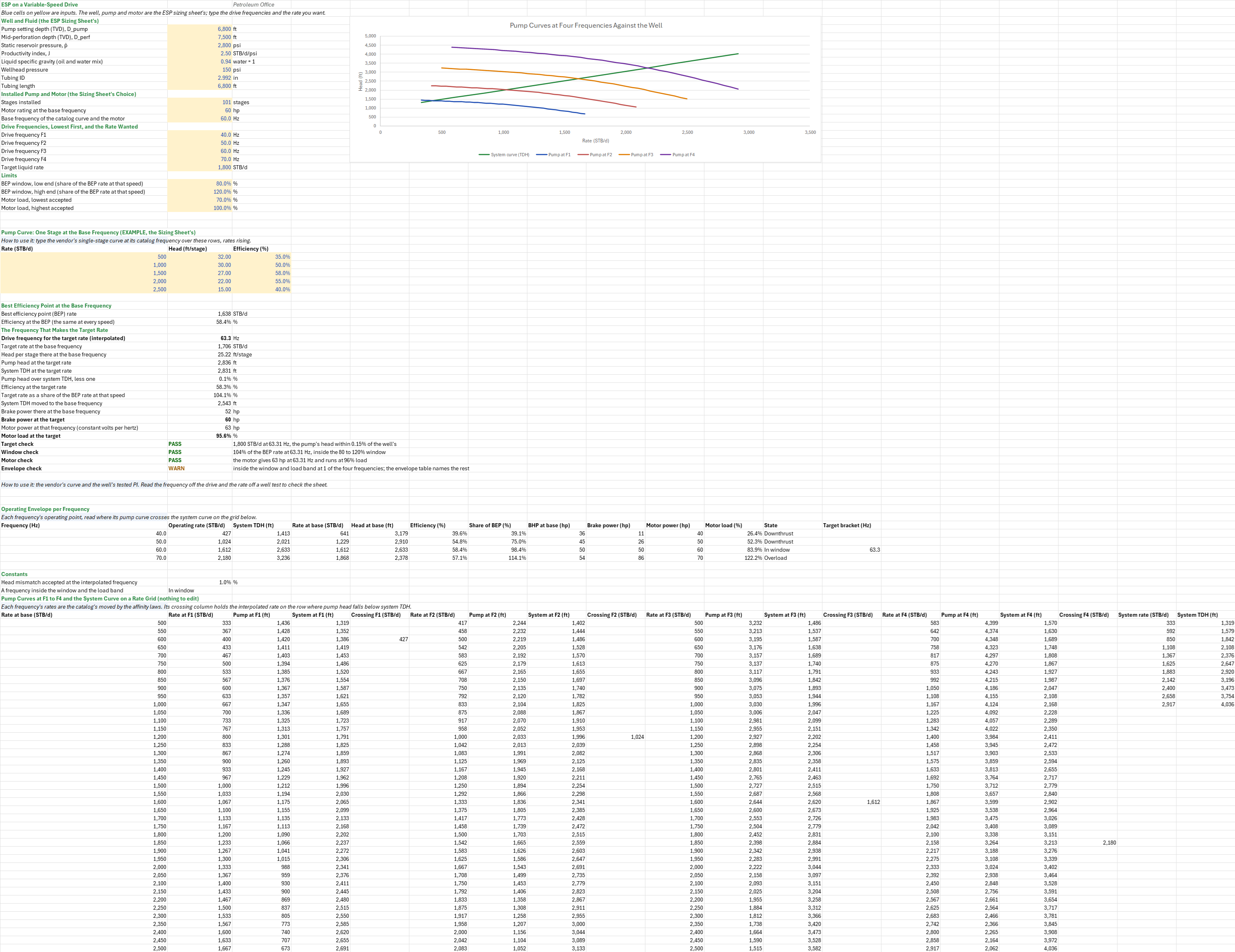
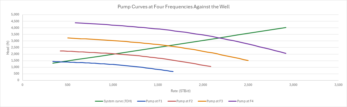
How to use it: The sheet takes the ESP Sizing and Operating Point sheet's well, pump curve, 101 stages and 60 hp motor and runs the pump at four drive frequencies, 40, 50, 60 and 70 Hz by default. Type in the vendor's single-stage curve at its catalog frequency and the well's tested PI. The pump curve ships as EXAMPLE data, the sizing sheet's. To check the sheet, read the frequency off the drive and the rate off a well test. The operating envelope has one row per frequency. One chart draws the four pump curves against the system curve. Four checks read the target, the BEP window and motor load at the target, and how many frequencies sit inside the window.
Method: At frequency f the pump's rate scales with f/fbase and its head with (f/fbase)², the affinity laws. The sheet takes a grid of 41 rates across the catalog curve at the base frequency, which is the sizing sheet's grid. It moves each rate to every frequency, and the installed head there is N times the base-frequency head per stage at the base rate, moved by the head affinity law. The system curve at each moved rate is the sizing sheet's: the PIP at p̄ − q/J less the fluid column to the pump, the tubing friction, and the TDH. The operating rate is the zero crossing of pump head less system TDH, interpolated between the two bracketing rows. At the base frequency this reproduces the sizing sheet's operating point to the digit.
Efficiency doesn't change along an affinity line, so the sheet moves each operating point back to the base frequency to read it there: the rate by fbase/f and the TDH by (fbase/f)². At that point it reads the efficiency, the share of the BEP rate, and the brake power from rate, head, SG and efficiency. It then moves the power to f by the cube of the speed ratio. That is the same power as the brake power from rate at f, because rate times head scales with the cube. The motor is taken at constant volts per hertz, so its power is its rating times f/fbase. The load is the brake power over that.
The target's frequency is linear between the two frequencies whose operating rates bracket it. At that frequency the sheet reads the pump's head at the target rate against the system's TDH. The difference shows how far the linear step is from the true crossing.
Example: The defaults are the sizing sheet's well and pump: 101 stages set at 6,800 ft, mid-perforations at 7,500 ft, p̄ 2,800 psi, J 2.5 STB/d/psi, SG 0.94, 150 psi at the wellhead, 2.992 in tubing, and the 60 hp motor.
- The frequencies:
- At 60 Hz the pump meets the well at 1,612.35 STB/d and 2,633 ft. That is 98 % of the BEP rate, with 50.3 hp at 84 % load, the sizing sheet's operating point.
- At 40 Hz it makes 427 STB/d at 39 % of its BEP rate, deep in downthrust.
- At 50 Hz it makes 1,024 STB/d at 75 %, still under the window.
- At 70 Hz it makes 2,180 STB/d at 114 %, inside the window, but the brake power is 85.5 hp against the motor's 70 hp at that speed, a 122 % load.
- Only 60 Hz is inside the window and the load band, so the envelope check warns.
- The target: 1,800 STB/d falls between 60 and 70 Hz, at 63.31 Hz. There the pump's head is within 0.15 % of the well's TDH, the rate is 104 % of the BEP rate at that speed, and the motor gives 63.3 hp and runs at 96 % load, inside the window and the load band.
Functions used
PO.ESP.Curve.BEP(curve_Q, curve_Eff)
Returns Best Efficiency Point flow rate from pump curve, [bbl/d].
PO.ESP.Curve.BEP.Eff(curve_Q, curve_Eff)
Returns maximum efficiency value from pump curve, [fraction].
PO.ESP.Curve.Head(Q, curve_Q, curve_Head, [extrapolate])
Interpolates head from pump performance curve, [ft/stage].
PO.ESP.Pump.TotalHead(stages, head_per_stage)
Calculates total head from number of stages, [ft].
PO.ESP.TDH(TVD_pump, WHP, PIP, friction_head, SG)
Calculates Total Dynamic Head for ESP sizing, [ft].
PO.ESP.Nodal.Psuction(D, Pwf, D_pump, SG)
Calculates the suction pressure of a pump set at a given depth, Pwf − 0.433·SG·(D − D_pump) (Economides Eq. 20-29); negative when the well cannot lift fluid to it, [psi].
PO.ESP.Nodal.Drawdown(Q, PI)
Calculates drawdown at given production rate, [psi].
PO.ESP.System.Hfric(Q, tubing_ID, tubing_length, SG)
Simplified friction head calculation, [ft].
PO.ESP.Curve.Efficiency(Q, curve_Q, curve_Eff, [extrapolate])
Interpolates efficiency from pump performance curve, [fraction].
PO.ESP.BrakeHP.FromRate(Q, TDH, SG, efficiency)
Calculates brake horsepower directly from rate and head, [hp].
PO.ESP.Motor.LoadFactor(BHP_required, motor_rating)
Calculates motor load as fraction of rating, [dimensionless].
Names (73)
| Name | Refers to | Comment |
|---|---|---|
PO.ESP.Affinity.RateLAMBDA |
=LAMBDA(q, f, f_base, q*f/f_base) |
Affinity law: rate at frequency f from the rate at f_base, in the units of q. |
PO.ESP.Affinity.HeadLAMBDA |
=LAMBDA(h, f, f_base, h*(f/f_base)^2) |
Affinity law: head at frequency f from the head at f_base, in the units of h. |
PO.ESP.Affinity.PowerLAMBDA |
=LAMBDA(p, f, f_base, p*(f/f_base)^3) |
Affinity law: power at frequency f from the power at f_base, in the units of p. |
VSD_Dpump |
$B$4 |
Pump setting depth (TVD), D_pump, ft |
VSD_Dperf |
$B$5 |
Mid-perforation depth (TVD), D_perf, ft |
VSD_Pr |
$B$6 |
Static reservoir pressure, p̄, psi |
VSD_PI |
$B$7 |
Productivity index, J, STB/d/psi |
VSD_SG |
$B$8 |
Liquid specific gravity (oil and water mix), water = 1 |
VSD_WHP |
$B$9 |
Wellhead pressure, psi |
VSD_TubID |
$B$10 |
Tubing ID, in |
VSD_TubL |
$B$11 |
Tubing length, ft |
VSD_N |
$B$13 |
Stages installed, stages |
VSD_Motor |
$B$14 |
Motor rating at the base frequency, hp |
VSD_Fb |
$B$15 |
Base frequency of the catalog curve and the motor, Hz |
VSD_F1 |
$B$17 |
Drive frequency F1, Hz |
VSD_F2 |
$B$18 |
Drive frequency F2, Hz |
VSD_F3 |
$B$19 |
Drive frequency F3, Hz |
VSD_F4 |
$B$20 |
Drive frequency F4, Hz |
VSD_Qt |
$B$21 |
Target liquid rate, STB/d |
VSD_BepLo |
$B$23 |
BEP window, low end (share of the BEP rate at that speed), % |
VSD_BepHi |
$B$24 |
BEP window, high end (share of the BEP rate at that speed), % |
VSD_LoadMin |
$B$25 |
Motor load, lowest accepted, % |
VSD_LoadMax |
$B$26 |
Motor load, highest accepted, % |
VSD_Inputs |
$B$4:$B$26 |
The well, the installed stages and motor, the base frequency, four drive frequencies, the target rate and the design limits |
VSD_PumpData |
$A$32:$C$36 |
The catalog curve at the base frequency: rate, head per stage and efficiency of one stage |
VSD_CurveQ |
$A$32:$A$36 |
Pump curve rates at the base frequency, STB/d |
VSD_CurveH |
$B$32:$B$36 |
Pump curve head per stage at the base frequency, ft/stage |
VSD_CurveE |
$C$32:$C$36 |
Pump curve efficiency, fraction |
VSD_QBEP |
$B$39 |
Best efficiency point (BEP) rate, STB/d |
VSD_EffBEP |
$B$40 |
Efficiency at the BEP (the same at every speed), % |
VSD_Ft |
$B$42 |
Drive frequency for the target rate (interpolated), Hz |
VSD_Qbt |
$B$43 |
Target rate at the base frequency, STB/d |
VSD_Hbt |
$B$44 |
Head per stage there at the base frequency, ft/stage |
VSD_Ht |
$B$45 |
Pump head at the target rate, ft |
VSD_TDHt |
$B$46 |
System TDH at the target rate, ft |
VSD_Mis |
$B$47 |
Pump head over system TDH, less one, % |
VSD_EffT |
$B$48 |
Efficiency at the target rate, % |
VSD_ShareT |
$B$49 |
Target rate as a share of the BEP rate at that speed, % |
VSD_TDHbt |
$B$50 |
System TDH moved to the base frequency, ft |
VSD_BHPbt |
$B$51 |
Brake power there at the base frequency, hp |
VSD_BHPt |
$B$52 |
Brake power at the target, hp |
VSD_MotorT |
$B$53 |
Motor power at that frequency (constant volts per hertz), hp |
VSD_LoadT |
$B$54 |
Motor load at the target, % |
VSD_TargetCheck |
$B$55 |
Target check verdict |
VSD_TargetCheckNote |
$C$55 |
Target check comment |
VSD_WindowCheck |
$B$56 |
Window check verdict |
VSD_WindowCheckNote |
$C$56 |
Window check comment |
VSD_MotorCheck |
$B$57 |
Motor check verdict |
VSD_MotorCheckNote |
$C$57 |
Motor check comment |
VSD_EnvelopeCheck |
$B$58 |
Envelope check verdict |
VSD_EnvelopeCheckNote |
$C$58 |
Envelope check comment |
VSD_Results |
$B$39:$B$58 |
The BEP, the frequency for the target rate with its head, efficiency, power and motor load, and the checks |
VSD_Envelope |
$A$66:$M$69 |
Each drive frequency's operating rate and TDH, the point moved to the base frequency, efficiency, share of the BEP rate, brake power, motor power and load, its state, and the target's bracket |
VSD_Q1 |
$B$66 |
Operating rate at F1, STB/d |
VSD_TDH1 |
$C$66 |
System TDH at the operating rate at F1, ft |
VSD_BHP1 |
$I$66 |
Brake power at F1, hp |
VSD_Load1 |
$K$66 |
Motor load at F1 |
VSD_Q2 |
$B$67 |
Operating rate at F2, STB/d |
VSD_TDH2 |
$C$67 |
System TDH at the operating rate at F2, ft |
VSD_BHP2 |
$I$67 |
Brake power at F2, hp |
VSD_Load2 |
$K$67 |
Motor load at F2 |
VSD_Q3 |
$B$68 |
Operating rate at F3, STB/d |
VSD_TDH3 |
$C$68 |
System TDH at the operating rate at F3, ft |
VSD_BHP3 |
$I$68 |
Brake power at F3, hp |
VSD_Load3 |
$K$68 |
Motor load at F3 |
VSD_Q4 |
$B$69 |
Operating rate at F4, STB/d |
VSD_TDH4 |
$C$69 |
System TDH at the operating rate at F4, ft |
VSD_BHP4 |
$I$69 |
Brake power at F4, hp |
VSD_Load4 |
$K$69 |
Motor load at F4 |
VSD_MisTol |
$B$72 |
Head mismatch accepted at the interpolated frequency, % |
VSD_InWindow |
$B$73 |
The state a frequency inside the BEP window and the motor's load band reads |
VSD_Grid |
$A$77:$S$117 |
The catalog rates, and at each drive frequency the rate, the installed pump's head, the system TDH and the crossing; then the system curve across all four |
VSD_SystemCurve |
$C$77:$S$87 |
Pump Curves at Four Frequencies Against the Well |
Details
| Inserts | 117 rows × 19 columns |
| Category | Electric Submersible Pump |
| For agents and tools | Descriptor (.md) |